60 V, 173 A, 3.3 mOhm — the conduction-loss floor
Its headline figure is a maximum Rds(on) of 3.3 mOhm at Vgs=10 V and Id=100 A — that's the voltage drop you pay per amp, and at 173 A continuous drain current the on-state dissipation stays under 100 W at 25°C case temperature. The 60 V drain-to-source rating puts it squarely in the 48 V bus / 12 V automotive / battery-switch class, not the 100 V+ motor-drive tier. The 210 nC total gate charge at Vgs=10 V tells you this is a high-gate-charge part — expect to budget a gate driver that can source several amps peak to hit the target switching frequency. At 100 kHz the average gate drive current is 21 mA, but the peak pulse current during the Miller plateau is what determines the rise time. Pair it with a driver rated for at least 2 A peak output.
Package and thermal reality — TO-262 through-hole
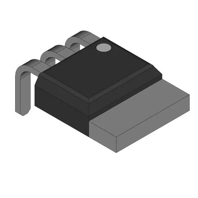
The TO-262AA (I²Pak) package is a through-hole variant of the D²Pak, with long leads that make it easier to hand-solder or rework than a surface-mount part. The exposed metal tab on the back is the drain — it needs a good thermal path to the heatsink. Mounting is through-hole, so the PCB needs drilled holes for the leads and a thermal pad or heatsink interface for the tab. The lead pitch and hole pattern follow the TO-262 standard — no special footprint beyond what any TO-220/TO-262 socket or solder pad provides.
For a drop-in replacement, confirm the TO-262 footprint and gate-drive requirements against the BOM.