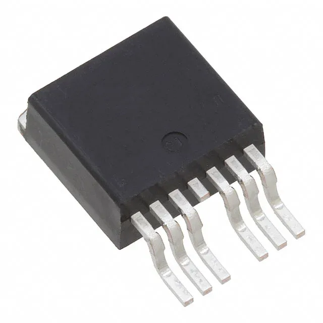
60 V, 240 A, 1.95 mOhm — where the StrongIRFET sits
The IRFS7534TRL7PP: The headline Rds(on) of 1.95 mOhm at 100 A with 10 V gate drive sets the conduction loss floor for a high-current OR-ing, motor-drive, or synchronous-rectification leg.
Total gate charge Qg is 300 nC at Vgs=10 V, with an input capacitance Ciss of 9990 pF at Vds=25 V. The 300 nC Qg means a 2 A gate driver can theoretically switch this FET at about 6.6 MHz, but practical hard-switching frequencies in a 60 V, 240 A design land closer to 200–500 kHz once the Miller plateau and layout parasitics are factored in. The 6 V and 10 V drive voltage thresholds for minimum and maximum Rds(on) mean a 10 V gate rail is strongly preferred; a 5 V logic-level drive will leave significant Rds(on) on the table.
Thermal envelope and junction rating
The 175°C Tj(max) qualifies this MOSFET for under-hood automotive and industrial environments where junction temperatures exceed 150°C under overload or fault conditions. The 7-lead variant is not pin-compatible with the standard 3-lead D2PAK.