75 V, 195 A — the low Rds(on) drives the selection
The headline spec is the 3 mOhm maximum on-resistance at Vgs = 10 V and Id = 140 A — this is the number that determines conduction losses in a high-current path like a motor drive, battery isolator, or DC-DC converter primary switch. At 75 V the part sits in the low-voltage, high-current class, distinct from higher-voltage CoolMOS parts that trade Rds(on) for breakdown voltage.
175 °C junction — thermal headroom for dense layouts
The 175 °C ceiling allows the part to run at higher case temperatures without derating the current as aggressively as a 150 °C-rated device — useful when the PCB copper area is limited or the ambient is high.
Gate charge and input capacitance — driver sizing
For a 100 kHz switching frequency, the average gate drive current needed is 240 nC × 100 kHz = 24 mA, but the peak current during switching transitions is much higher — a 2 A gate driver is a practical minimum to keep switching losses under control. The 9370 pF input capacitance also means the driver must supply enough instantaneous current to charge that capacitance within the desired dead-time window.
D2PAK (TO-263) — surface-mount power package
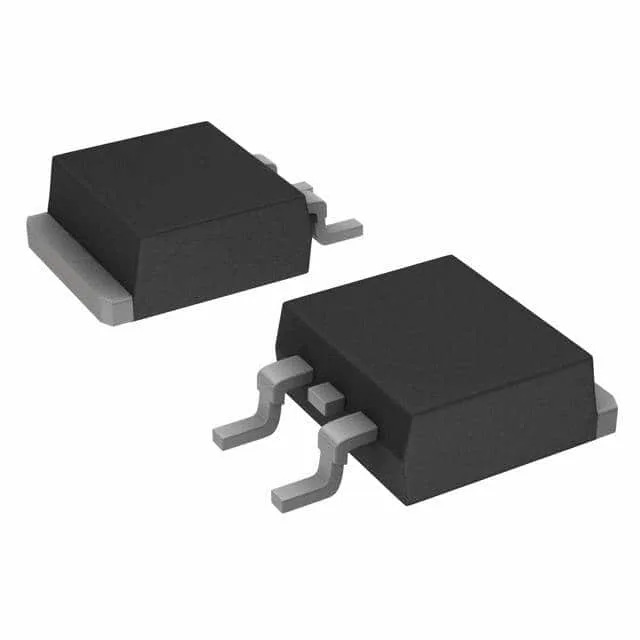
The IRFS3107TRLPBF comes in the D2PAK (TO-263-3) surface-mount package with two leads plus the tab. The Tape & Reel option (TR suffix) is the volume-production format.
The ROHS3 compliance is confirmed, covering the full substance restriction list including the four phthalates.