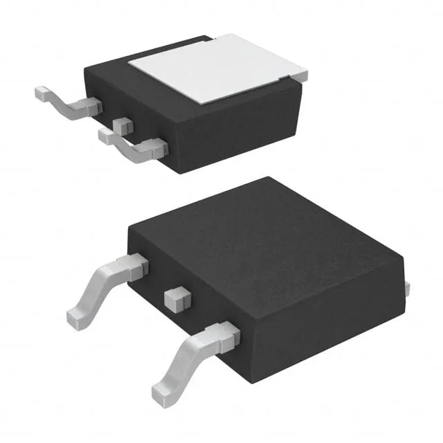
Infineon Technologies IRFR9120NTRLPBF

IRFR9120NTRLPBF P-Channel MOSFET, 100V 6.6A DPAK

MPNIRFR9120NTRLPBF
End of Life

Infineon IRFR9120NTRLPBF, HEXFET® P-Channel MOSFET, 100 V Vdss, 6.6 A Id, 480 mOhm Rds(on) at 10 V, D-Pak (TO-252), -55°C to 150°C, Tape & Reel.

$1.05Ref. price · indicative, final on quote
PackagingTO-252-3, DPak (2 Leads + Tab), SC-63
RoHSROHS3 Compliant
SeriesHEXFET®
Independent supplier — new & surplus stockAuthenticity-screened · ESD-safe packingListing updated Jul 2026

Specifications

IRFR9120NTRLPBF specifications
ParameterValue
SeriesHEXFET®
FET typeP-Channel
MountingSurface Mount
Drain to source voltage100 V
Drive voltage (Max rds on, min rds on)10V
Current - continuous drain (Id) @ 25°C6.6A (Tc)
Power dissipation40W (Tc)
Operating temperature-55°C ~ 150°C (TJ)
PackageTape & Reel (TR); Cut Tape (CT)
Vgs±20V
TechnologyMOSFET (Metal Oxide)
CaseTO-252-3, DPak (2 Leads + Tab), SC-63
Vgs(th) (Max) @ id4V @ 250µA
Rds on (Max) @ id, vgs480mOhm @ 3.9A, 10V
Gate charge (Qg) (Max) @ vgs27 nC @ 10 V
Input capacitance (Ciss) (Max) @ vds350 pF @ 25 V

Product details

The IRFR9120NTRLPBF is a 100 V P-channel MOSFET from Infineon's HEXFET family, rated for 6.6 A continuous drain current at 25°C case temperature. Packaged in a surface-mount D-Pak (TO-252), it is designed for high-side load switching, battery protection, and DC-DC converter applications where a positive supply rail needs to be switched off. The P-channel polarity simplifies gate drive — no charge pump needed when the source is tied to the positive rail — making it a common choice for automotive body controllers, industrial solenoid drivers, and power management in telecom line cards.

The 27 nC gate charge at 10 V keeps gate-drive losses manageable in PWM applications switching at tens of kilohertz; input capacitance of 350 pF at 25 V Vds means the driver sees a moderate load, compatible with most gate-driver ICs.

Frequently asked questions

What is the Rds(on) of IRFR9120NTRLPBF?

The maximum on-resistance is 480 mOhm at a gate-to-source voltage of 10 V and a drain current of 3.9 A. This is the figure used for conduction loss calculations in the design.