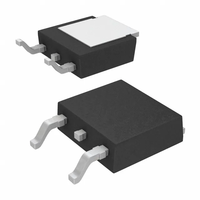
Infineon Technologies IRFR7540TRPBF

IRFR7540TRPBF N-Channel MOSFET, 60 V, 90 A, 4.8 mOhm

MPNIRFR7540TRPBF
End of Life

Infineon StrongIRFET series, IRFR7540TRPBF, N-Channel MOSFET, 60 V Vdss, 90 A Id, 4.8 mOhm Rds(on), D-PAK (TO-252AA) surface-mount package.

$1.4Ref. price · indicative, final on quote
PackagingTO-252-3, DPak (2 Leads + Tab), SC-63
StockContact for availability
MOQ1 pcs
  • 100% new & originalTraceable channels only — no refurbs, no pulls, no remarked parts.
  • Date & lot codes on quoteStated per line before you commit; label photos on request.
  • MSL-compliant ESD packingMoisture-sealed bags with indicator cards; reels photo-verified.
  • PayPal buyer protectionPay by T/T, PayPal or Payoneer — card payments covered end to end.

Specifications

IRFR7540TRPBF Technical Specifications
ParameterValue
SeriesStrongIRFET™
FET typeN-Channel
Mounting typeSurface Mount
Drain to source voltage60 V
Drive voltage (Max rds on, min rds on)6V, 10V
Current - continuous drain (Id) @ 25°C90A (Tc)
Power dissipation140W (Tc)
Operating temperature-55°C ~ 175°C (TJ)
PackageTape & Reel (TR); Cut Tape (CT)
Vgs±20V
TechnologyMOSFET (Metal Oxide)
CaseTO-252-3, DPak (2 Leads + Tab), SC-63
Vgs(th) (Max) @ id3.7V @ 100µA
Rds on (Max) @ id, vgs4.8mOhm @ 66A, 10V
Gate charge (Qg) (Max) @ vgs130 nC @ 10 V
Input capacitance (Ciss) (Max) @ vds4360 pF @ 25 V

Product details

60 V, 90 A, 4.8 mOhm — StrongIRFET power switch

The IRFR7540TRPBF: The D-PAK (TO-252AA) surface-mount package suits automated assembly on standard PCB footprints with a copper-pad thermal land for heat spreading.

Gate charge and switching profile

Total gate charge Qg is 130 nC at 10 V — a moderate figure for a 90 A FET, meaning the gate driver must source around 1.3 A peak to hit a 100 ns rise time. The input capacitance Ciss is 4360 pF at 25 V drain bias, which sets the driver's dynamic current draw and the switching edge rate. The recommended drive voltage window is 6 V to 10 V for achieving the rated Rds(on) minimum and maximum.

Package and thermal interface

The TO-252-3 (DPak) package has a single exposed tab on the back side — the drain terminal. For the PCB layout engineer: the copper pad under the tab must be sized to the 140 W power dissipation rating at the case; a 1-oz copper pour of at least 8 cm² per side is a starting point for 25°C ambient still-air conditions, though the actual derating follows the junction-to-ambient thermal resistance curve.

Lifecycle and sourcing

No official second-source or pin-compatible alternate is listed in the manufacturer's cross-reference data.

Frequently asked questions

What is the datasheet for IRFR7540TRPBF?

Design engineers need complete electrical characteristics and recommended operating conditions.

Is the IRFR7540TRPBF obsolete or still active?

Brokers and buyers need to know product lifecycle to avoid supply chain risks.

Where can I buy IRFR7540TRPBF?

Sourcing buyers want trusted distributors with real-time inventory and competitive pricing.

What is the price of IRFR7540TRPBF in volume?

Procurement teams need cost data for BOM cost estimation and negotiation.

What is the equivalent part for IRFR7540TRPBF?

Engineers and buyers need drop-in alternatives when primary part is unavailable or premium priced.

What is the pin configuration of IRFR7540TRPBF?

Maintenance techs and layout designers need to verify footprint compatibility for replacement or new design.