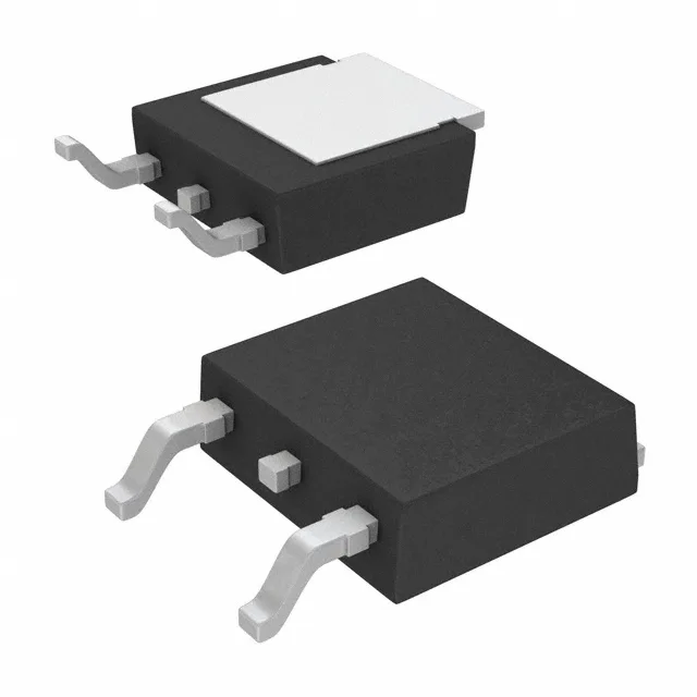
Infineon Technologies IRFR48ZTRPBF

IRFR48ZTRPBF MOSFET N-CH 55V 42A DPAK, 11mOhm Rds(on)

MPNIRFR48ZTRPBF
End of Life

Infineon HEXFET® IRFR48ZTRPBF N-channel MOSFET, 55 V drain-source, 42 A continuous drain, 11 mOhm max Rds(on) at 10 V gate drive, D-Pak surface-mount package, -55°C to 175°C junction temperature.

$1.37Ref. price · indicative, final on quote
PackagingTO-252-3, DPak (2 Leads + Tab), SC-63
StockContact for availability
MOQ1 pcs
  • 100% new & originalTraceable channels only — no refurbs, no pulls, no remarked parts.
  • Date & lot codes on quoteStated per line before you commit; label photos on request.
  • MSL-compliant ESD packingMoisture-sealed bags with indicator cards; reels photo-verified.
  • PayPal buyer protectionPay by T/T, PayPal or Payoneer — card payments covered end to end.

Specifications

IRFR48ZTRPBF Technical Specifications
ParameterValue
SeriesHEXFET®
FET typeN-Channel
Mounting typeSurface Mount
Drain to source voltage55 V
Drive voltage (Max rds on, min rds on)10V
Current - continuous drain (Id) @ 25°C42A (Tc)
Power dissipation91W (Tc)
Operating temperature-55°C ~ 175°C (TJ)
PackageTape & Reel (TR); Cut Tape (CT)
Vgs±20V
TechnologyMOSFET (Metal Oxide)
CaseTO-252-3, DPak (2 Leads + Tab), SC-63
Vgs(th) (Max) @ id4V @ 50µA
Rds on (Max) @ id, vgs11mOhm @ 37A, 10V
Gate charge (Qg) (Max) @ vgs60 nC @ 10 V
Input capacitance (Ciss) (Max) @ vds1720 pF @ 25 V

Product details

55 V, 42 A N-channel — the D-Pak switch for high-current rails

The D-Pak (TO-252) footprint keeps the board area tight for a part this current-dense.

Gate charge and switching — sizing the driver

Total gate charge is 60 nC at 10 V. For a 100 kHz switching frequency, the average gate-drive current needed is 60 nC × 100 kHz = 6 mA — well within a standard gate-driver IC's capability. The 1720 pF input capacitance at 25 V drain-source gives a sense of the switching energy per cycle; the driver must source and sink that charge through the gate loop inductance without ringing.

Temperature range — rated for the harsh stuff

Junction temperature range is -55°C to 175°C, which puts this part in the military/industrial temperature grade. That 175°C ceiling suits engine-bay electronics, downhole tools, and avionics power stages where ambient heat pushes junction temperatures past the usual 150°C limit.

Package and mounting

Surface-mount D-Pak (TO-252) with two leads and a tab. Rework is straightforward with hot air: preheat the board to 100°C, hit the tab with 350°C air, lift when the solder flows. The tab orientation is marked by a chamfer on the package body — easy to see under magnification.

Lifecycle — still in active production

ROHS3 compliant.

Frequently asked questions

What is the Rds(on) of IRFR48ZTRPBF?

Maximum on-resistance is 11 mOhm at 37 A drain current with 10 V gate-to-source drive. This is the figure to use for conduction-loss calculations at full load.

Is IRFR48ZTRPBF equivalent to IPD50R950CEAUMA1?

No — these are different parts for different voltage classes. The IRFR48ZTRPBF is a 55 V, 42 A, 11 mOhm N-channel HEXFET in D-Pak. The IPD50R950CEAUMA1 is a 500 V, 4.3 A, 950 mOhm CoolMOS CE in the same package. They are not functional equivalents; the voltage and current ratings differ by an order of magnitude.

What is the gate charge of IRFR48ZTRPBF?

Maximum total gate charge is 60 nC at 10 V gate-to-source voltage. This value determines the gate-driver current requirement for a given switching frequency.