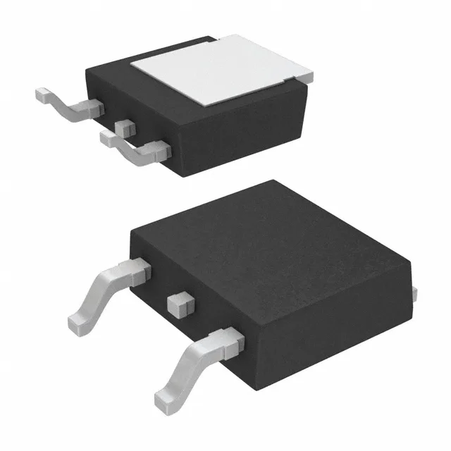
150 V, 33 A, 42 mOhm — sizing the power switch
The 42 mOhm maximum on-resistance at Vgs=10 V and 21 A sets the conduction loss floor for a secondary-side synchronous rectifier, a DC-DC converter output switch, or a motor-drive half-bridge leg.
Gate drive budget and switching loss
Total gate charge is 26 nC at Vgs=10 V, and input capacitance Ciss is 1750 pF at Vds=50 V. For a 100 kHz switching frequency the gate driver must supply an average current of about 2.6 mA just to charge and discharge the gate — well within a standard totem-pole driver like the TC4427, but the peak current still needs to be sized for the gate resistance and the driver's output stage. The ±20 V maximum gate-source rating means a 12 V or 15 V gate drive is safe; a 10 V drive is specified for the rated Rds(on). If the design uses a 5 V logic-level gate drive, the on-resistance will be higher than the datasheet maximum — the 5 V threshold is a max of 5 V at 100 µA, so a 5 V gate drive leaves almost no overdrive margin.
DPak footprint and thermal path
The Cut Tape option is available for prototyping quantities.