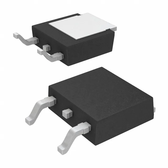
Infineon Technologies IRFR4510TRPBF

Infineon IRFR4510TRPBF N-Channel MOSFET, 100V 56A D-Pak

MPNIRFR4510TRPBF
End of Life

Infineon HEXFET series IRFR4510TRPBF, N-Channel MOSFET, 100V Vdss, 56A Id, 13.9 mOhm Rds(on) @ 10V, 81 nC Qg, TO-252-3 D-Pak, -55°C to 175°C.

$1.84Ref. price · indicative, final on quote
PackagingTO-252-3, DPak (2 Leads + Tab), SC-63
StockContact for availability
MOQ1 pcs
  • 100% new & originalTraceable channels only — no refurbs, no pulls, no remarked parts.
  • Date & lot codes on quoteStated per line before you commit; label photos on request.
  • MSL-compliant ESD packingMoisture-sealed bags with indicator cards; reels photo-verified.
  • PayPal buyer protectionPay by T/T, PayPal or Payoneer — card payments covered end to end.

Specifications

IRFR4510TRPBF Technical Specifications
ParameterValue
SeriesHEXFET®
FET typeN-Channel
Mounting typeSurface Mount
Drain to source voltage100 V
Drive voltage (Max rds on, min rds on)10V
Current - continuous drain (Id) @ 25°C56A (Tc)
Power dissipation143W (Tc)
Operating temperature-55°C ~ 175°C (TJ)
PackageTape & Reel (TR); Cut Tape (CT)
Vgs±20V
TechnologyMOSFET (Metal Oxide)
CaseTO-252-3, DPak (2 Leads + Tab), SC-63
Vgs(th) (Max) @ id4V @ 100µA
Rds on (Max) @ id, vgs13.9mOhm @ 38A, 10V
Gate charge (Qg) (Max) @ vgs81 nC @ 10 V
Input capacitance (Ciss) (Max) @ vds3031 pF @ 50 V

Product details

100V, 56A N-channel — the D-Pak workhorse for motor-drive and DC-DC stages

The IRFR4510TRPBF: It targets the 48V–72V bus range common in e-bike controllers, telecom DC-DC converters, and industrial 24V–48V motor drives where the 100V drain-source voltage gives headroom for inductive load transients. The 13.9 mOhm maximum Rds(on) at Vgs=10V and 38A sets the conduction loss floor — at 56A the I²R loss hits 43W, which the 143W package power dissipation can handle with adequate PCB copper area and airflow.

Gate charge and switching — 81 nC at 10V gate drive

Total gate charge Qg is 81 nC at 10V gate drive. The 3031 pF input capacitance at 50V Vds is the Miller plateau capacitance the driver sees during the switching transition. The ±20V maximum gate-source voltage gives margin above the 10V recommended drive level, but the 4V threshold at 100 µA means the device is fully enhanced only above 6V — never run it at 5V gate drive and expect the rated Rds(on).

175°C junction — rated for under-hood and industrial thermal cycling

The -55°C to 175°C junction temperature range qualifies this part for under-hood automotive and industrial drives in non-conditioned enclosures. The 175°C TJ(max) is the hard ceiling for die temperature. ROHS3 compliant, so it qualifies for EU RoHS and China RoHS markets without exemption paperwork.

D-Pak footprint — tab soldered to copper pour

The TO-252-3 D-Pak package has two source leads and a drain tab. The tab is the primary thermal path — the PCB footprint must include a copper pour area under the tab to keep the junction temperature below 175°C at full load.

Frequently asked questions

What is the Rds(on) of the IRFR4510TRPBF at 10V gate drive?

Maximum on-resistance is 13.9 milliohms at 38A drain current with a 10V gate-source voltage. That is the figure to use for worst-case conduction loss calculations at 25°C junction — at 125°C junction the Rds(on) typically increases by 50-60%.

Is the IRFR4510TRPBF compatible with 100V systems?

Yes, the drain-source breakdown voltage (Vdss) is rated at 100V minimum. This gives adequate margin for 48V and 72V bus systems. For 100V rails the derating is tight — ensure the peak drain voltage including ringing stays below 80V to keep a 20% margin on the 100V rating.