That is manageable for most half-bridge gate-driver ICs, but at 500 kHz the 50 mA gate-drive current starts to push the driver's output stage — budget a driver with at least 2 A peak source/sink if you plan to switch above 200 kHz.
Thermal and package — DPak rework and board-level reality
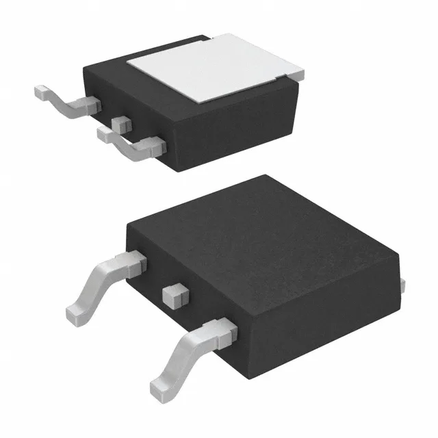
The DPak (TO-252-3) surface-mount package has an exposed tab on the bottom — the drain connection. A 1-inch-square copper pour under the tab with thermal vias to an internal ground plane brings the junction-to-ambient resistance down to about 40°C/W. Without that copper area, the 140 W dissipation rating is academic — you will hit the 175°C junction limit at a fraction of that power. The DPak is hand-solderable with a hot-air station — the tab reflows well with paste under it, and the three leads are easy to inspect. The tab is the drain, so the PCB landing pad must be isolated from other nets unless the drain is common. No orientation mark ambiguity — the tab is the drain side.
Temperature grade — military-range junction capability
The 175°C TJ(max) is the silicon limit, not the package limit — the DPak's solder-joint reliability at that temperature depends on the PCB's CTE match and the solder alloy. For continuous operation above 150°C junction, use a high-temperature solder (SAC305 or higher) and avoid thermal cycling that exceeds 100°C delta.
ROHS3 compliant per the current revision. No official second-source or cross-reference is listed on the Infineon portfolio for this exact order code.