5 mOhm at 20 A — the conduction loss floor
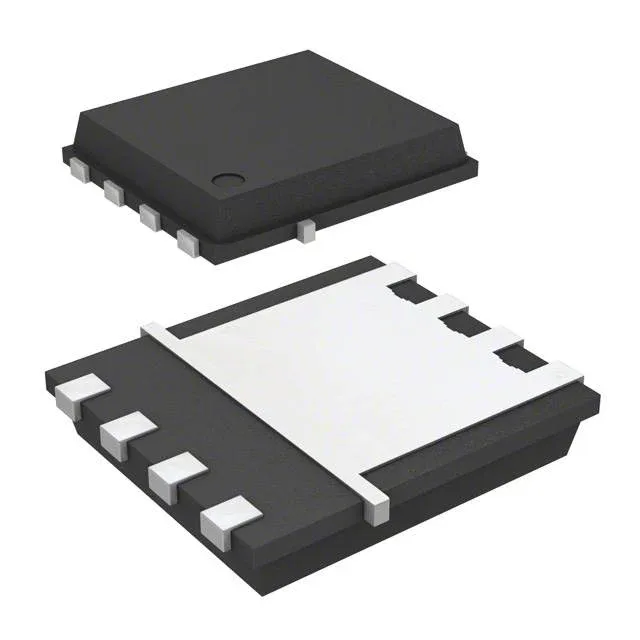
The IRFH8325TRPBF is a 30 V, N-Channel HEXFET power MOSFET in the 8-PowerTDFN (PQFN 5x6) package. Its headline on-resistance is 5 mOhm max at Vgs=10 V and Id=20 A — the figure that sets the I²R conduction loss in a synchronous buck or load switch. At 20 A the drop is 100 mV, which keeps die temperature rise manageable even with the 3.6 W (Ta) / 54 W (Tc) dissipation ceiling.
Gate charge and drive voltage flexibility
Total gate charge is 32 nC at Vgs=10 V. That is a moderate figure — a 1 A gate driver at 500 kHz switching frequency would burn about 16 mA of drive current from the bias rail, leaving headroom for the driver's own losses. The drive voltage range spans 4.5 V to 10 V (min and max Rds(on) points), so the part works with either 5 V logic-level gate drive or a standard 10 V rail. Below 4.5 V the on-resistance climbs steeply — the 2.35 V threshold at 50 µA is a weak turn-on, not a logic-level guarantee.
Current rating — Ta vs Tc matters
That 4× spread reflects the thermal resistance difference: 3.6 W max in still air vs 54 W when the PQFN exposed pad is soldered to a copper plane. For a real BOM, the usable current is the lower of the two unless the board has a dedicated heatsink or forced airflow.
The 8-PowerTDFN (PQFN 5x6) has a large exposed pad on the bottom. The 2487 pF input capacitance at Vds=10 V is moderate — the gate driver sees a ~32 nC charge packet, so rise/fall times in the 10–20 ns range are achievable with a 2 A driver.
It is ROHS3 compliant. The HEXFET series is an established Infineon (formerly International Rectifier) trench MOSFET family; no official second-source cross-reference is listed in the procurement data, so dual-sourcing would require qualifying a pin-compatible N-channel from another vendor with similar Rds(on) and Qg.