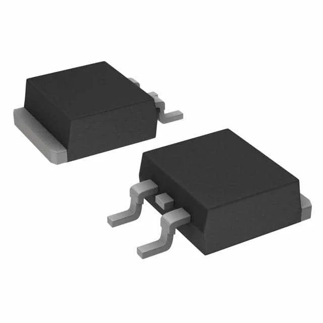
Infineon Technologies IRF8010STRLPBF

IRF8010STRLPBF HEXFET N-Channel MOSFET, 100V 80A D2PAK

MPNIRF8010STRLPBF
End of Life

Infineon HEXFET N-channel MOSFET, IRF8010STRLPBF, 100V Vdss, 80A Id, 15mOhm Rds(on) at 10V, D2PAK surface-mount package, -55°C to 175°C junction temperature.

$2.7Ref. price · indicative, final on quote
PackagingTO-263-3, D²Pak (2 Leads + Tab), TO-263AB
StockContact for availability
MOQ1 pcs
  • 100% new & originalTraceable channels only — no refurbs, no pulls, no remarked parts.
  • Date & lot codes on quoteStated per line before you commit; label photos on request.
  • MSL-compliant ESD packingMoisture-sealed bags with indicator cards; reels photo-verified.
  • PayPal buyer protectionPay by T/T, PayPal or Payoneer — card payments covered end to end.

Specifications

IRF8010STRLPBF Technical Specifications
ParameterValue
SeriesHEXFET®
FET typeN-Channel
Mounting typeSurface Mount
Drain to source voltage100 V
Drive voltage (Max rds on, min rds on)10V
Current - continuous drain (Id) @ 25°C80A (Tc)
Power dissipation260W (Tc)
Operating temperature-55°C ~ 175°C (TJ)
PackageTape & Reel (TR); Cut Tape (CT)
Vgs±20V
TechnologyMOSFET (Metal Oxide)
CaseTO-263-3, D²Pak (2 Leads + Tab), TO-263AB
Vgs(th) (Max) @ id4V @ 250µA
Rds on (Max) @ id, vgs15mOhm @ 45A, 10V
Gate charge (Qg) (Max) @ vgs120 nC @ 10 V
Input capacitance (Ciss) (Max) @ vds3830 pF @ 25 V

Product details

100 V, 80 A N-channel HEXFET in D2PAK

It comes in a D2PAK (TO-263) surface-mount package, designed for high-current switching applications where board space is tight but thermal performance still matters — the large copper tab on the D2PAK pulls heat into the PCB plane.

15 mOhm Rds(on) — what it means for conduction loss

The on-resistance is 15 mOhm maximum at 45 A drain current with 10 V gate drive. At 45 A, that works out to roughly 30 W conduction loss at the hot junction — the 260 W package dissipation rating (at case temperature) gives enough thermal headroom for a properly heatsunk design, but the junction temperature derating curve is the real limiter in continuous operation.

Gate charge and switching drive

Total gate charge is 120 nC at 10 V, with an input capacitance of 3830 pF at 25 V drain-source. For a 100 kHz switching frequency, the average gate drive current needed is about 12 mA — a standard MOSFET gate driver handles that comfortably. The ±20 V maximum gate-source rating gives margin for ringing on long gate traces in a motor-drive or power-supply layout.

Temperature range and application fit

Junction temperature range is -55°C to 175°C, covering military and industrial extremes. That makes it suitable for under-hood automotive, industrial motor drives, telecom rectifiers, and battery management systems where the ambient can push past 85°C and the MOSFET sees self-heating on top. The 4 V maximum gate threshold at 250 µA drain current means it needs a 10 V gate drive to hit the rated Rds(on) — a 5 V logic-level drive will leave it partially enhanced and running hot.

Active production — no LTB concern

It is ROHS3 compliant, and the D2PAK package is a standard surface-mount format that remains widely used in power designs.

Frequently asked questions

What is the Rds(on) of IRF8010STRLPBF?

The maximum on-resistance is 15 mOhm at 45 A drain current with 10 V gate drive. This is the figure to use for worst-case conduction loss calculations in your thermal design.

What is the gate charge of IRF8010STRLPBF?

Total gate charge is 120 nC at 10 V gate-source voltage. This determines the gate drive current needed for your switching frequency — for example, at 100 kHz the average drive current is about 12 mA.