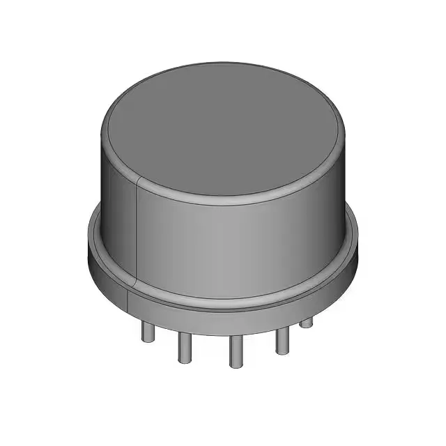
Infineon Technologies IRF6711STRPBF — Discrete Semiconductors

IRF6711STRPBF N-Channel MOSFET, 25 V, 3.8 mOhm Rds(on)

MPNIRF6711STRPBF
Active

Infineon IRF6711STRPBF, N-Channel MOSFET, 25 V, 19 A, 3.8 mOhm Rds(on) at 10 V, DirectFET surface-mount package, -40°C to 150°C junction temperature.

$0.81Ref. price · indicative, final on quote
StockContact for availability
MOQ1 pcs
  • 100% new & originalTraceable channels only — no refurbs, no pulls, no remarked parts.
  • Date & lot codes on quoteStated per line before you commit; label photos on request.
  • MSL-compliant ESD packingMoisture-sealed bags with indicator cards; reels photo-verified.
  • PayPal buyer protectionPay by T/T, PayPal or Payoneer — card payments covered end to end.

Specifications

IRF6711STRPBF Technical Specifications
ParameterValue
SeriesDirectFET™
FET typeN-Channel
Mounting_typeSurface Mount
Operating temperature high-40°C to 150°C(TJ)
Vgs±20 V
Power_w2.2
Package_typeBulk
Capacitance_uf0.0018
Product_statusActive
Supply_voltage_v25.0
Vgs(Th) (Max) @ id2.35 V @ 25µA
Switching_current_a19.0
Rds on (Max) @ id, vgs3.8mOhm @ 19 A, 10 V
Gate charge (Qg) (Max) @ vgs20 nC @ 4.5 V

Product details

Active production — no end-of-life watch needed

The IRF6711STRPBF: No LTB window or last-time-buy deadline to track for this order code.

3.8 mOhm Rds(on) at 10 V — the conduction loss floor

The on-resistance is specified at 3.8 mOhm maximum when the gate is driven to 10 V and the drain carries 19 A. That is the number to use for the I²R conduction loss calculation at full load; at lower gate voltages the resistance rises, so a 5 V logic drive will see a higher effective Rds(on). The 25 V drain-source rating and 19 A continuous current envelope suit this part for 12 V to 24 V rail switching, OR-ing diodes, and low-voltage DC-DC converter synchronous rectification.

DirectFET can — layout and thermal handling

The DirectFET package is a metal can with the drain tab on top and source/gate pads underneath. The PCB copper area under the can is the primary heatsink — the datasheet's thermal resistance figures assume a specific pad geometry, so the board layout directly sets the junction temperature. At 2.2 W dissipation the can will run hot without adequate copper pour or airflow. Gate drive threshold is 2.35 V maximum at 25 µA drain current, and the absolute maximum gate-source voltage is ±20 V. A 10 V gate drive is the recommended operating point for the rated Rds(on); a 5 V logic signal will still turn the FET on hard enough for most loads, but the on-resistance will be higher than the 3.8 mOhm figure.

Switching speed and gate drive budget

Total gate charge is 20 nC at 4.5 V, which means a 1 A gate driver can switch the FET in roughly 20 ns. The 19 A continuous rating and 84 A pulsed current (from the description) make this a capable part for hard-switched converters up to a few hundred kilohertz, provided the gate drive loop is kept tight.

Frequently asked questions

What is the Rds(on) of IRF6711STRPBF?

The maximum Rds(on) is 3.8 mOhm at Vgs = 10 V and Id = 19 A. That is the conduction loss figure to use for the worst-case thermal calculation.

Does IRF6711STRPBF require a heatsink?

The DirectFET package relies on the PCB copper pour for heat spreading. At 2.2 W dissipation, adequate copper area on the board is essential — without it the junction temperature will exceed the 150 °C maximum under continuous full load.