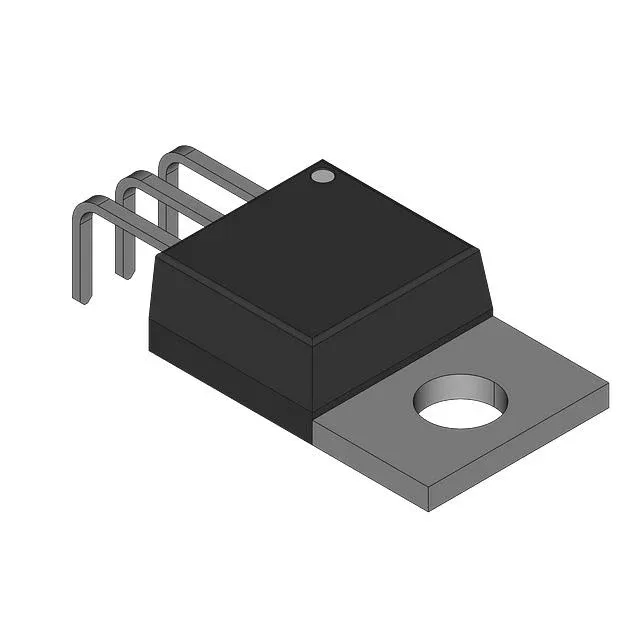
450 V, 4.5 A N-channel — sizing the TO-3 for the job
The IRF431 is an N-channel power MOSFET in a TO-3 through-hole package, rated for 450 V drain-source and 4.5 A continuous drain current. That 450 V ceiling puts it squarely in offline power-conversion territory — flyback converters, PFC stages, and high-voltage DC-DC supplies in industrial gear. The TO-3 case is a two-screw mount with a steel cap; you need a mica insulator and thermal grease if the heatsink is grounded, and the tab is the drain, so the mounting hardware must not short to chassis.
Rds(on) and gate drive — the thermal budget
On-resistance is 1.5 Ohm maximum at 2.5 A drain current with 10 V on the gate. That is not a low-Rds(on) part — at 4.5 A the conduction loss hits 30 W, so the TO-3 flange must be bolted to a heatsink sized for that dissipation. Gate threshold is 4 V at 250 µA, but to fully enhance the channel you need the full 10 V drive; a 5 V logic-level gate driver will leave it in the linear region and cook the die. Total gate charge is 30 nC at 10 V, which is modest — a standard gate-driver IC or even a discrete totem-pole can switch it at tens of kHz without excessive drive loss.
Junction temperature and field survival
The practical limit in a repair scenario is the case-to-ambient thermal resistance — the TO-3 package relies on the metal flange to sink heat. If the original heatsink is corroded or the thermal compound dried out, the junction will hit 150°C well below 4.5 A. In a field swap, clean the mounting surface and apply fresh grease; the two 4-40 screws need 6-8 in-lb torque — no more, or you crack the ceramic foot.
Sourcing — still active, no LTB pressure
For a legacy repair, you are not forced into the surplus market yet, though the TO-3 package is less common in new consumer gear.