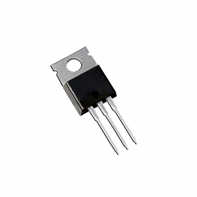
Total gate charge is 68 nC at 10 V. The drive voltage range is specified from 6 V (minimum for rated Rds(on)) to 10 V (for the full 4.5 mOhm). A 12 V gate drive is fine within the ±20 V Vgs max, but the 10 V figure is the one to design to for the datasheet Rds(on) number.
175 °C junction — where this part lives
That 175 °C ceiling is a step above the common 150 °C limit — it suits under-hood automotive, engine-bay, or industrial enclosures where ambient air hits 85 °C and the heatsink sees 100 °C. The 83 W power dissipation at case temperature is the thermal budget; at 50 A continuous with 4.5 mOhm, conduction loss is about 11.25 W, leaving headroom for switching losses before the junction reaches 175 °C.
This is a low-voltage, high-current switch. The 40 V Vdss ceiling means it belongs in 12 V, 24 V, or 36 V rails — not a 48 V telecom bus (which needs 60 V or 80 V rated parts). Typical applications include brushed and brushless DC motor drivers, secondary-side synchronous rectification in 12 V output power supplies, battery-management load switches, and low-voltage inverter stages.