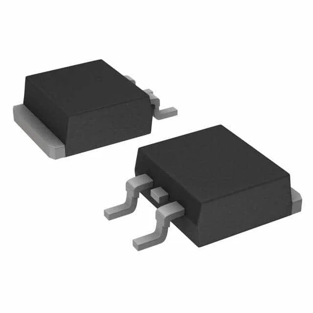
Package and mounting
The 160 W power dissipation rating at the case tells you the thermal design needs a solid thermal pad and via array under the tab to keep junction temperature below the 175 °C absolute maximum.
Gate charge and switching — sizing the driver
Total gate charge is 120 nC at 10 V. At a 100 kHz switching frequency, the average gate drive current needed is 12 mA — well within a typical MOSFET driver's capability, but the peak current from the driver must handle the gate capacitance charging in the transition time. The 2900 pF input capacitance at 25 V drain-source confirms the gate is not excessively large; a standard 1 A to 2 A gate driver will switch this part cleanly in a hard-switching topology.
Package and mounting
Surface-mount D2PAK (TO-263-3) with two leads and a tab. Preheating the board to 125 °C before hot-air removal prevents the tab from wicking heat away and cracking the solder joint on the opposite side. The tab's thermal mass means a standard hot-air station at 350 °C with a 10 mm nozzle will lift the part cleanly if the board is preheated; without preheat, expect to chase a cold joint on the tab.
