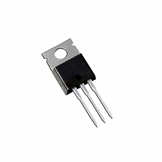
Infineon Technologies IRF2804PBF

IRF2804PBF HEXFET N-Channel MOSFET, 40V 75A TO-220AB

MPNIRF2804PBF
End of Life

Infineon HEXFET IRF2804PBF, N-Channel MOSFET, 40 V Vdss, 75 A continuous drain, 2.3 mOhm Rds(on) at 10 V, 240 nC gate charge, TO-220AB through-hole, -55 to 175 °C.

$3.54Ref. price · indicative, final on quote
PackagingTO-220-3
StockContact for availability
MOQ1 pcs
  • 100% new & originalTraceable channels only — no refurbs, no pulls, no remarked parts.
  • Date & lot codes on quoteStated per line before you commit; label photos on request.
  • MSL-compliant ESD packingMoisture-sealed bags with indicator cards; reels photo-verified.
  • PayPal buyer protectionPay by T/T, PayPal or Payoneer — card payments covered end to end.

Specifications

IRF2804PBF Technical Specifications
ParameterValue
SeriesHEXFET®
FET typeN-Channel
Mounting typeThrough Hole
Drain to source voltage40 V
Drive voltage (Max rds on, min rds on)10V
Current - continuous drain (Id) @ 25°C75A (Tc)
Power dissipation300W (Tc)
Operating temperature-55°C ~ 175°C (TJ)
PackageTube
Vgs±20V
TechnologyMOSFET (Metal Oxide)
CaseTO-220-3
Vgs(th) (Max) @ id4V @ 250µA
Rds on (Max) @ id, vgs2.3mOhm @ 75A, 10V
Gate charge (Qg) (Max) @ vgs240 nC @ 10 V
Input capacitance (Ciss) (Max) @ vds6450 pF @ 25 V

Product details

Package and mounting

The IRF2804PBF is an N-channel HEXFET from Infineon, rated 40 V drain-source and 75 A continuous drain at 25 °C case temperature. The headline number is the 2.3 mOhm maximum on-resistance at Vgs = 10 V and 75 A — that is about the resistance of a few centimetres of heavy-gauge wire. In a high-current switching circuit like a DC motor drive or a battery disconnect, that low Rds(on) keeps conduction losses low enough that the TO-220AB package can handle 300 W dissipation with adequate heatsinking.

Gate charge and driver sizing

Gate charge is 240 nC max at Vgs = 10 V. That is a substantial charge — the gate driver must source and sink that charge each switching cycle. At 100 kHz, the average gate drive current is 24 mA; at 200 kHz it doubles to 48 mA. A standard logic-level gate driver will struggle; plan on a dedicated driver with at least 2 A peak output to keep switching edges clean and avoid Miller-turn-on issues.

Temperature range and field deployment

That is military-grade thermal headroom — the part can sit in an engine bay, a downhole tool, or an outdoor telecom rectifier without derating at the hot end. The 175 °C limit also means the thermal interface to the heatsink must be managed: the 300 W dissipation rating assumes the case is held at 25 °C, so in practice the real power limit is set by the heatsink and airflow.

Sourcing and lifecycle posture

ROHS3 compliant. The part is a through-hole TO-220AB, which means it is field-replaceable with basic tools: a soldering iron and a desoldering pump are enough to swap it on site.

Frequently asked questions

What is the Rds(on) of the IRF2804PBF?

Maximum on-resistance is 2.3 mOhm at Vgs = 10 V and Id = 75 A. That is the value used for conduction-loss calculations in a high-current switch.

What is the gate charge of the IRF2804PBF?

Maximum total gate charge is 240 nC at Vgs = 10 V. This determines the gate-drive current required at your switching frequency.