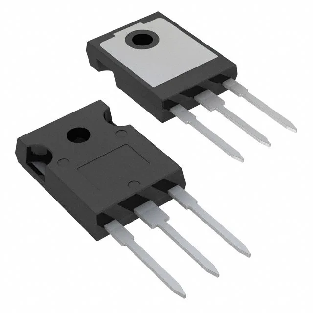
Infineon Technologies IRF250P224

IRF250P224 N-Channel MOSFET, 250V 96A TO-247AC

MPNIRF250P224
End of Life

Infineon StrongIRFET™ IRF250P224, N-Channel MOSFET, 250V Vdss, 96A Id, 12mOhm Rds(on) at 10V, TO-247AC through-hole package, -55°C to 175°C junction temperature.

$9.92Ref. price · indicative, final on quote
PackagingTO-247-3
StockContact for availability
MOQ1 pcs
  • 100% new & originalTraceable channels only — no refurbs, no pulls, no remarked parts.
  • Date & lot codes on quoteStated per line before you commit; label photos on request.
  • MSL-compliant ESD packingMoisture-sealed bags with indicator cards; reels photo-verified.
  • PayPal buyer protectionPay by T/T, PayPal or Payoneer — card payments covered end to end.

Specifications

IRF250P224 Technical Specifications
ParameterValue
SeriesStrongIRFET™
FET typeN-Channel
Mounting typeThrough Hole
Drain to source voltage250 V
Drive voltage (Max rds on, min rds on)10V
Current - continuous drain (Id) @ 25°C96A (Tc)
Power dissipation313W (Tc)
Operating temperature-55°C ~ 175°C (TJ)
PackageTube
Vgs±20V
TechnologyMOSFET (Metal Oxide)
CaseTO-247-3
Vgs(th) (Max) @ id4V @ 270µA
Rds on (Max) @ id, vgs12mOhm @ 58A, 10V
Gate charge (Qg) (Max) @ vgs203 nC @ 10 V
Input capacitance (Ciss) (Max) @ vds9915 pF @ 50 V

Product details

250 V, 96 A, 12 mOhm — high-current switching MOSFET

The 12 mOhm maximum on-resistance at Vgs=10 V and 58 A sets the conduction loss floor for a high-current switching stage. The 203 nC gate charge at Vgs=10 V means the gate driver must supply enough peak current to charge and discharge the gate within the target switching dead-time. At 100 kHz switching, the average gate-drive current is about 20 mA, but the peak current from the driver needs to be several amperes to keep switching losses under control. The 9915 pF input capacitance at Vds=50 V is a direct consequence of the large die needed for the 96 A rating. This capacitance dominates the switching speed; a gate-driver with at least 2 A peak source/sink capability is recommended for hard-switched applications above 50 kHz.

Through-hole TO-247AC — thermal and assembly considerations

The TO-247AC through-hole package (three leads, isolated tab) is designed for bolting to a heatsink. The 313 W maximum power dissipation at case temperature assumes the case is held at 25°C — in practice, the junction-to-case thermal resistance sets the real power limit for the chosen heatsink and airflow.

Frequently asked questions

What is the Rds(on) of IRF250P224?

The maximum on-resistance is 12 mOhm at Vgs=10 V and Id=58 A. This is the value to use for worst-case conduction loss calculations at the rated drive voltage.