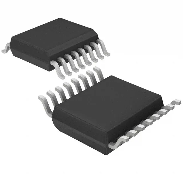
IR2113SPBF

Infineon Technologies

Infineon IR2113SPBF half-bridge gate driver, 600 V bootstrap, 2 A peak source/sink, 3.3 V to 20 V supply, non-inverting inputs, independent channels, surface mount 16-SOIC, -40°C to 150°C operating junction temperature.

Infineon Technologies IR2113SPBF
[IN STOCK] In Stock: 32 pcs
$2.53/ pc

Volume pricing

Buy Now

MOQ 1 · Tube · RoHS · EIA-481 · DAP/DDP · T/T

Technical specifications

IR2113SPBF specifications
Parameter / AttributeSpecification / Value
Gate typeIGBT, N-Channel MOSFET
Input typeNon-Inverting
Channel typeIndependent
MountingSurface Mount
Supply voltage3.3V ~ 20V
Logic voltage - VIL, VIH6V, 9.5V
High side voltage - max (Bootstrap)600 V
Current - peak output (Source, sink)2A, 2A
Operating temperature-40°C~150°C(TJ)
PackageTube
Case16-SOIC (0.295\", 7.50mm Width)
Number of drivers2
Driven configurationHalf-Bridge
Rise (Fall time)25ns, 17ns
100% Footprint Match · Solder-Ready (No PCB Redesign Needed)

Need Stock or a Drop-in Second-Source for IR2113SPBF?

Package: DIP-14 / SOIC-16 · Pin-compatible replacements with immediate Shenzhen spot stock

Footprint Match 98%
Supply Chain & Allocation Reality:

The IR2110 is the gate driver that half the worlds inverters, welders, motor drives and induction cookers were built around - a 14-pin part with an independent high and low channel, a floating bootstrap supply for the high side, and enough drive for the workhorse IGBTs and MOSFETs of two decades. The family splits by the one number that matters at the rail: IR2110 carries a 500V offset, IR2113 a 600V offset, and everything else - pins, drive current, logic - is shared. The buying story has a modern chapter too: Infineons IRS2110/IRS2113 are pin-to-pin successors with a tighter internal clamp, and a row of third-party equivalents (the FAN7392, the TF2110 class) keeps the socket servable from multiple lines.

Verified Pin-Compatible Replacements (4 verified alternatives)

IR2113 Infineon (IR) DIP-14 / SOIC-16
100% Drop-in (Zero Code Change)
Availability & Target Pricing:

The 600V Member of the Same Die

Shenzhen Spot Stock (24-48h Dispatch)

Electrical & Core Specs:

Same driver design as the IR2110 with the offset raised to 600V (VB absolute max 625V against 525V): identical pins, identical +/-2A drive, independent high and low channels, bootstrap floating supply.

Gate drive 10V to 20V per channel; logic inputs 3.3V-compatible.

Compatibility & Drop-In Notes: The substitution rule of this family: the 600V part replaces the 500V part anywhere; the reverse is only safe when the actual bus transients stay inside the lower rating. Pick by measured rail peaks, not by nominal bus voltage.
Package & Solder Footprint: Pin-for-pin in both DIP-14 and SOIC-16 outlines.
Shenzhen Warehouse Stock & MOQ: Stocked as a pair; the 2113 is the safer default in mains-derived designs.
IRS2110 Infineon DIP-14 / SOIC-16
Pin-to-Pin (Minor Clock/Init Tuning)
Availability & Target Pricing:

The Modern Successor Line

Shenzhen Spot Stock (24-48h Dispatch)

Electrical & Core Specs:

The pin-to-pin successor generation: same block diagram and pins with tighter specifications and an internal 20V clamp on all supplies.

The clamp changes the absolute maximums: supply pins end at 20V instead of 25V - a bench supply or bootstrap overshoot that a plain IR2110 survived can damage the IRS part.

Compatibility & Drop-In Notes: A documented direct replacement with one discipline: verify the supply rails sit inside the tighter clamp. In most existing designs nothing changes; in designs that leaned on the old headroom, the review is the job.
Package & Solder Footprint: Same DIP-14 / SOIC-16 pinout.
Shenzhen Warehouse Stock & MOQ: Active Infineon production; the long-term buy for the socket.
FAN7392 onsemi (Fairchild line) DIP-14 / SOIC-16
Functional Equivalent
Availability & Target Pricing:

The Fairchild-Line Equivalent

Shenzhen Spot Stock (24-48h Dispatch)

Electrical & Core Specs:

The Fairchild/onsemi member of the 2110-class: independent high and low channels, bootstrap high side, engineered against the same socket and application set.

Same gate-drive envelope; verify the offset rating of the exact variant against the bus.

Compatibility & Drop-In Notes: Verify offset rating and propagation specs against the original before fleet substitution; the family resemblance is strong but the numbers are the contract.
Package & Solder Footprint: 14-pin DIP / 16-pin SOIC family outlines.
Shenzhen Warehouse Stock & MOQ: Second-source line stock; useful when the IR parts are allocated.
TF2110 TF Semiconductor DIP-14 / SOIC-16
Functional Equivalent
Availability & Target Pricing:

The Cost-Line Drop-In

Shenzhen Spot Stock (24-48h Dispatch)

Electrical & Core Specs:

A Chinese-fab equivalent explicitly listed against IR2110/IR2113/IRS2113 class sockets for price-driven builds and repair volume.

Same functional envelope; validate per-lot against the original switching behavior.

Compatibility & Drop-In Notes: The economics make sense in repair and consumer goods: verify the offset class and the drive current on the exact datasheet, and screen lots - this class of part is where relabeling lives.
Package & Solder Footprint: Standard family pinout; confirm the package variant on the orderable number.
Shenzhen Warehouse Stock & MOQ: Volume pricing; stocked with photographed markings.
Buyer & Quality Checklist for Sourcing Alternatives
  • Pick by offset class against measured bus peaks: 500V (IR2110) or 600V (IR2113) - mains-derived rails and inductive loads regularly spike above the nominal figure.
  • The bootstrap supply is a design, not a pin: the bootstrap capacitor, the gate resistors and the VS node layout decide whether the high side survives negative transients. When a driver dies repeatedly on the same board, look at the bootstrap network before the part.
  • IRS2110/IRS2113 carry a 20V clamp on the supplies instead of 25V: check the rails and the bootstrap overshoot before substituting, especially where a bench supply or transients previously had headroom.
  • IR2104-class parts are single-input half-bridge drivers with internal deadtime and lower output current - a different family. A design wired for independent HIN/LIN control does not want one.
  • At power-up, the low side must initialize before the high side can bootstrap: startup sequences that skip this produce silent high-side failure - a classic when a repaired board works at the bench and fails in the enclosure.
  • For fleet repairs, keep VBS within ratings during negative-bus recovery events: the successor datasheets spell out the Rg/CB/layout conditions, and they apply to every member of the family.
Frequently Asked Technical Questions

Q: What is the difference between IR2110 and IR2113?

A: Only the high-side offset rating: 500V against 600V, plus a tighter delay-matching spec on the 2113. Pins, drive current and logic are identical, and the 600V part substitutes for the 500V part everywhere.

Q: Is IRS2110 a drop-in replacement for IR2110?

A: Pin-to-pin and documented as such, with one discipline: the supplies are clamped at 20V instead of 25V, so verify rail and bootstrap voltages sit inside the tighter limit.

Q: Why does the high-side channel keep failing in my inverter repair?

A: Usually the bootstrap path: capacitor value and ESR, VS node layout and negative transient recovery. The driver absorbs the event first. Fix the bootstrap network and the board, or the new part dies the same way.

Technical details

Half-bridge driver with 2 A peak drive and 600 V bootstrap

The Infineon IR2113SPBF is a half-bridge gate driver designed to drive IGBTs and N-channel MOSFETs in high-side/low-side configurations. It delivers 2 A peak source and sink current, enough to charge and discharge the gate capacitance of medium-power switching devices in motor drives, inverters, and switch-mode power supplies. The bootstrap supply handles rail voltages up to 600 V, and the driver runs from a single 3.3 V to 20 V bias rail, so it works with both 5 V logic controllers and traditional 15 V gate-drive supplies.

The independent channel architecture lets you adjust each channel's timing separately. The non-inverting input logic simplifies the control interface — a high on the input turns the corresponding output on directly. Logic thresholds at 6 V (VIL) and 9.5 V (VIH) are compatible with 5 V and 3.3 V logic when the supply is 12 V or higher; at lower supply voltages, verify the VIH margin against your controller's output-high level.

For new designs, the part is a current-production choice with no immediate supply risk.

IR2113SPBF
[ALLOC] verified
Quote