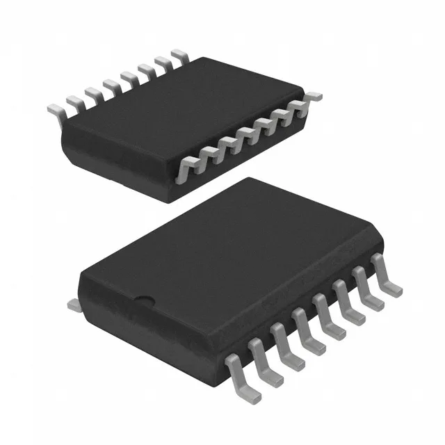
Half-bridge driver with 500 V bootstrap — what it drives and where
The Infineon IR2110SPBF is a high-voltage half-bridge gate driver designed to drive IGBTs and N-Channel MOSFETs in a half-bridge configuration. Its bootstrap supply handles up to 500 V on the high side, making it a fit for motor-drive inverters, UPS systems, and switch-mode power supplies where the DC bus sits in the 200 V to 400 V range. The two independent channels each source and sink 2 A peak, enough to charge and discharge the gate capacitance of medium-power switching devices in the 20 A to 50 A class.
3.3 V to 20 V supply — one driver, multiple bias rails
The supply range from 3.3 V to 20 V lets this part work with 5 V logic from an MCU or DSP, a 12 V automotive battery rail, or a 15 V industrial bias supply — all on the same BOM line. The logic input thresholds are set at 6 V (VIL) and 9.5 V (VIH), which means the driver accepts standard 5 V and 3.3 V logic levels without external level shifting, as long as the logic supply is referenced to the same ground.
25 ns rise, 17 ns fall — switching speed and dead-time planning
Typical rise time of 25 ns and fall time of 17 ns (into a standard test load) mean the driver can switch IGBT gates quickly enough for PWM frequencies up to about 100 kHz in practice. The asymmetric rise/fall favours faster turn-off, which helps reduce cross-conduction during dead-time intervals. The designer should budget a dead-time of at least 100 ns in the PWM controller to prevent shoot-through, especially when driving large IGBTs with higher gate charge.
Package and temperature — 16-SOIC with 150°C junction
The wide temperature grade is a genuine differentiator — many competing half-bridge drivers stop at 125°C.