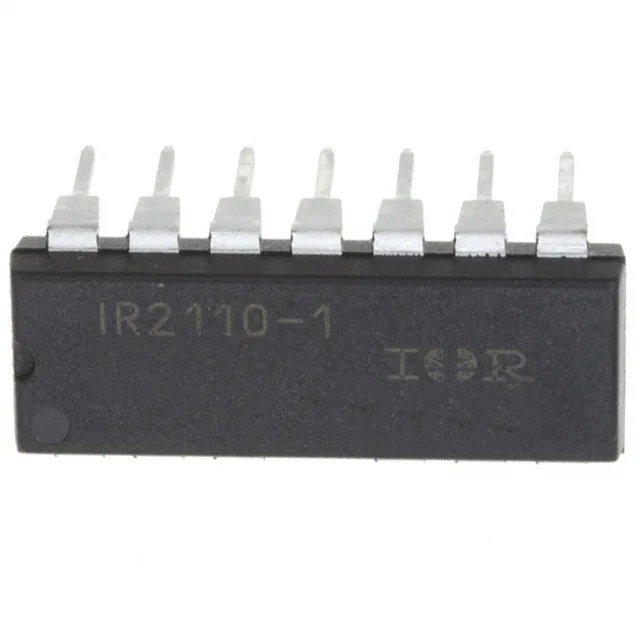
Half-bridge gate driver for IGBT and N-channel MOSFET power stages
The Infineon IR2110-1PBF is a high-voltage half-bridge gate driver designed to drive IGBTs and N-channel MOSFETs in a half-bridge configuration, with independent high- and low-side output channels. It delivers a 2A peak output current for both source and sink, which is enough to charge and discharge the gate capacitance of medium-power IGBTs and MOSFETs within the 25 ns typical rise and 17 ns fall times. The bootstrap high-side supply is rated to 500 V, setting the maximum DC bus voltage the power stage can handle. A wide supply range from 3.3V to 20V lets the driver accept logic-level inputs from a 3.3V controller or a 5V/15V gate-drive rail without an external level shifter.
The 2A peak source and sink current is the key rating for gate drive strength. At 25 ns rise and 17 ns fall times into a typical IGBT gate charge, the driver can switch the power device at frequencies up to several hundred kilohertz without excessive switching losses. The non-inverting input type means the output follows the input logic level directly — no inversion to account for in the control loop.
500 V bootstrap — the bus voltage ceiling
The 500 V maximum high-side voltage (bootstrap) sets the absolute maximum DC bus voltage for the half-bridge. For a 400 VDC bus, this part has 100 V of headroom; for a 600 V bus, a higher-voltage driver is needed. The logic input thresholds are 6V for VIL and 9.5V for VIH, which means a standard 5V logic output may not reliably drive the input high — a 12V or 15V gate-drive supply rail is typical.
For new designs, consider the current-production IR2110 series variants in the same 14-PDIP footprint, or a pin-compatible alternative from a second-source manufacturer.
14-PDIP through-hole package — board-level fit
The 14-PDIP (0.300-inch body width, 7.62 mm) through-hole package is a standard DIP footprint. The 13-lead variant omits one pin — confirm the PCB footprint matches the 13-lead layout before ordering.