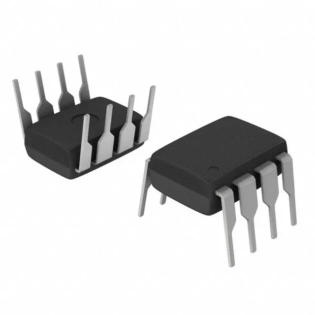
Half-bridge gate driver for 600 V bus applications
It drives both an N-channel MOSFET and an IGBT, with independent inverting and non-inverting input channels — so one input flips polarity while the other follows, which simplifies dead-time insertion in complementary switching stages.
210/360 mA peak output — what it buys you
The 210 mA source and 360 mA sink peak current determine how fast the gate capacitance charges and discharges. For a typical 10 nC gate charge, the rise time is about 100 ns and fall time 50 ns — fast enough for switching frequencies in the tens of kHz without excessive cross-conduction losses. If your IGBT or MOSFET has a total gate charge above 100 nC, the driver will still switch it, but the transition times stretch and the dead-time margin narrows.
Supply rail and logic thresholds
The driver operates from a 10 V to 20 V bias supply. The 600 V high-side bootstrap rating means the floating high-side driver can reference a switching node that swings up to 600 V above the low-side ground, which covers the majority of three-phase motor-drive and UPS inverter rails.
Sourcing is through independent distribution — stock is available on the spot market, and we quote each order against the BOM quantity. The 8-PDIP package is a through-hole form factor that suits rework and prototype builds as well as legacy production runs.