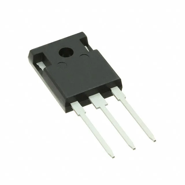
Infineon Technologies IPW60R041P6FKSA1

IPW60R041P6FKSA1 CoolMOS P6 N-Ch 600V 77.5A TO-247-3

MPNIPW60R041P6FKSA1
End of Life

Infineon CoolMOS™ P6 series, N-Channel MOSFET, 600 V Vdss, 77.5 A continuous drain, 41 mOhm Rds(on) at 10 V, 170 nC gate charge, TO-247-3 through-hole package, -55 to 150 °C junction temperature.

$12.45Ref. price · indicative, final on quote
PackagingTO-247-3
StockContact for availability
MOQ1 pcs
  • 100% new & originalTraceable channels only — no refurbs, no pulls, no remarked parts.
  • Date & lot codes on quoteStated per line before you commit; label photos on request.
  • MSL-compliant ESD packingMoisture-sealed bags with indicator cards; reels photo-verified.
  • PayPal buyer protectionPay by T/T, PayPal or Payoneer — card payments covered end to end.

Specifications

IPW60R041P6FKSA1 Technical Specifications
ParameterValue
SeriesCoolMOS™ P6
FET typeN-Channel
Mounting typeThrough Hole
Drain to source voltage600 V
Drive voltage (Max rds on, min rds on)10V
Current - continuous drain (Id) @ 25°C77.5A (Tc)
Power dissipation481W (Tc)
Operating temperature-55°C ~ 150°C (TJ)
PackageTube
Vgs±20V
TechnologyMOSFET (Metal Oxide)
CaseTO-247-3
Vgs(th) (Max) @ id4.5V @ 2.96mA
Rds on (Max) @ id, vgs41mOhm @ 35.5A, 10V
Gate charge (Qg) (Max) @ vgs170 nC @ 10 V
Input capacitance (Ciss) (Max) @ vds8180 pF @ 100 V

Product details

600 V, 41 mOhm — the conduction-loss floor for a 400 V bus

The IPW60R041P6FKSA1: The 77.5 A continuous drain rating at 25 °C case temperature is package-limited; the 481 W dissipation ceiling at Tc means real-world current in a 100 °C ambient is derated well below that figure. Plan the heatsink around the application's RMS current and the junction-to-case thermal resistance, not the 77.5 A headline.

170 nC gate charge — sizing the gate driver

With a total gate charge of 170 nC at 10 V, this FET needs a driver capable of sourcing and sinking that charge at the target switching frequency. At 100 kHz, the average gate current is 17 mA; at 200 kHz it doubles to 34 mA. The driver's peak current rating and its own thermal dissipation must cover the switching losses from charging and discharging that 8180 pF input capacitance at the switching node voltage.

Through-hole TO-247-3 — mounting and thermal interface

The PG-TO247-3 package is a through-hole footprint with a large metal tab for heatsink mounting.

Frequently asked questions

What is the Rds(on) of the IPW60R041P6FKSA1?

The maximum Rds(on) is 41 mOhm at 35.5 A drain current and 10 V gate drive. This is the conduction-loss floor at 25 °C junction temperature; on-resistance increases with temperature per the normalised curve in the datasheet.

Is the IPW60R041P6FKSA1 RoHS compliant?

Yes, it is listed as ROHS3 Compliant.

Can the IPW60R041P6FKSA1 be used for high-frequency switching?

It can be used, but the 170 nC gate charge and 8180 pF input capacitance mean the gate driver must supply the required peak current at the target frequency. At 100 kHz the average gate current is 17 mA; at 200 kHz it is 34 mA. The switching losses from charging and discharging that capacitance at 600 V will dominate the dissipation at higher frequencies. For very high frequency (500 kHz+) designs, a CoolMOS™ P7 or a SiC FET with lower Qg may be a better fit.