100 V, 2 mOhm — why this Rds(on) matters for your switching stage
The IPT020N10N5ATMA1 is an Infineon OptiMOS™5 N-channel MOSFET with a maximum drain-to-source voltage of 100 V and a maximum on-resistance of 2 mOhm at 150 A drain current with 10 V gate drive. That 2 mOhm figure is the number that sets the conduction loss floor in a high-current 48 V bus converter, a 12 V automotive alternator rectifier stage, or an 80 V intermediate rail where every milliohm costs watts in the thermal budget.
Current rating — case temperature vs. ambient
The continuous drain current is rated 260 A at the case (Tc) and 31 A at ambient (Ta) at 25°C. The 31 A ambient figure is the real-world limit for a bare board with no heatsink; the 260 A case rating assumes the package bottom is held at 25°C through a thermal interface to a cold plate or large copper area.
Gate charge and drive voltage
For a 100 kHz hard-switching stage, that means 15.2 mA average gate-drive current from the driver IC. The drive voltage range (6 V to 10 V for minimum Rds(on)) lets the designer trade gate-drive rail complexity against conduction loss — 10 V gives the full 2 mOhm, while 6 V still achieves the rated on-resistance at a slightly higher value. The ±20 V Vgs max provides margin for ringing on the gate node in a fast-switching layout.
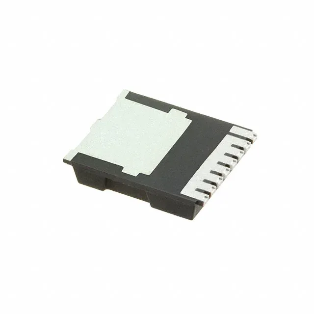
The PG-HSOF-8-1 package (8-PowerSFN) is a surface-mount HSOF with an exposed drain pad on the bottom.