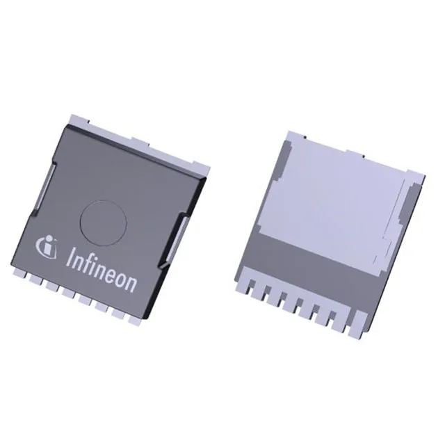
Infineon Technologies IPT012N08NF2SATMA1

IPT012N08NF2SATMA1 N-Channel MOSFET, 80 V, 1.23 mOhm

MPNIPT012N08NF2SATMA1
End of Life

Infineon StrongIRFET™ 2 IPT012N08NF2SATMA1, N-Channel MOSFET, 80 Vdss, 1.23 mOhm max Rds(on) at 150 A, 255 nC gate charge, PG-HSOF-8 surface-mount package, -55 to 175°C junction.

$5.47Ref. price · indicative, final on quote
Packaging8-PowerSFN
StockContact for availability
MOQ1 pcs
  • 100% new & originalTraceable channels only — no refurbs, no pulls, no remarked parts.
  • Date & lot codes on quoteStated per line before you commit; label photos on request.
  • MSL-compliant ESD packingMoisture-sealed bags with indicator cards; reels photo-verified.
  • PayPal buyer protectionPay by T/T, PayPal or Payoneer — card payments covered end to end.

Specifications

IPT012N08NF2SATMA1 Technical Specifications
ParameterValue
SeriesStrongIRFET™ 2
FET typeN-Channel
Mounting typeSurface Mount
Drain to source voltage80 V
Drive voltage (Max rds on, min rds on)6V, 10V
Current - continuous drain (Id) @ 25°C39A (Ta), 351A (Tc)
Power dissipation3.8W (Ta), 300W (Tc)
Operating temperature-55°C ~ 175°C (TJ)
PackageTape & Reel (TR); Cut Tape (CT)
Vgs±20V
TechnologyMOSFET (Metal Oxide)
Case8-PowerSFN
Vgs(th) (Max) @ id3.8V @ 267µA
Rds on (Max) @ id, vgs1.23mOhm @ 150A, 10V
Gate charge (Qg) (Max) @ vgs255 nC @ 10 V
Input capacitance (Ciss) (Max) @ vds12000 pF @ 40 V

Product details

80 V, 1.23 mOhm — the conduction-loss floor for high-current switching

That sub-milliohm Rds(on) sets the conduction-loss floor for high-current switching stages — synchronous rectification in a 48 V output converter, a motor-drive H-bridge, or a battery disconnect switch.

351 A at case — package-limited, not die-limited

The continuous drain current rating splits into two numbers: 39 A at 25°C ambient (Ta) and 351 A at 25°C case temperature (Tc). The 351 A figure is the package-limited capability when the case is held at 25°C — achievable only with a low-thermal-resistance path to a heatsink or cold plate. In still air on a standard PCB, the 39 A Ta rating is the practical ceiling. The 300 W power dissipation at Tc and 3.8 W at Ta frame the same thermal envelope: the PG-HSOF-8 package can shed 300 W into the board and heatsink if the thermal vias and copper area are sized for it.

175°C junction — headroom for under-hood and motor-drive environments

That extra headroom matters in automotive under-hood compartments, industrial motor drives with high ambient temperatures, or any enclosure where the junction temperature approaches the derating curve. The 3.8 V maximum gate threshold at 267 µA is a standard logic-level threshold — the part is specified for a 6 V to 10 V drive range for minimum Rds(on).

PG-HSOF-8 footprint — thermal via array is non-negotiable

The 8-PowerSFN package (PG-HSOF-8) is a surface-mount power package with an exposed drain pad on the bottom. The 12000 pF input capacitance at 40 V Vds sets the gate-drive loop impedance; a gate resistor in the 2–10 Ohm range is typical to control ringing without slowing the switching edge excessively.

Frequently asked questions

What are the detailed specifications of IPT012N08NF2SATMA1?

The continuous drain current is 39 A at ambient and 351 A at case temperature. The package is PG-HSOF-8 (8-PowerSFN).

Is IPT012N08NF2SATMA1 RoHS compliant?

Yes, it is ROHS3 compliant, meeting the latest EU restriction on hazardous substances in electrical and electronic equipment.

What are typical applications for IPT012N08NF2SATMA1?

The 80 V rating and sub-milliohm Rds(on) suit it for high-current switching stages: synchronous rectification in 48 V output converters, motor-drive H-bridges, battery disconnect switches, and high-power DC-DC converters in industrial and automotive environments where the 175°C junction temperature provides thermal headroom.