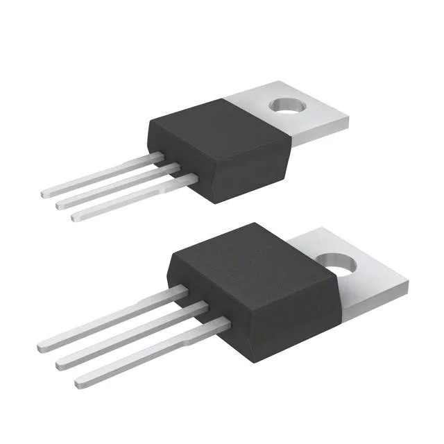
Infineon Technologies IPP70N10S3L12AKSA1

Infineon IPP70N10S3L12AKSA1 N-Channel MOSFET

MPNIPP70N10S3L12AKSA1
End of Life

Infineon OptiMOS IPP70N10S3L12AKSA1, N-channel MOSFET, 100V Vdss, 70A continuous drain, 12.1mOhm Rds(on) at 10V, 80nC gate charge, TO-220-3 through-hole, -55°C to 175°C junction.

$2.85Ref. price · indicative, final on quote
PackagingTO-220-3
StockContact for availability
MOQ1 pcs
  • 100% new & originalTraceable channels only — no refurbs, no pulls, no remarked parts.
  • Date & lot codes on quoteStated per line before you commit; label photos on request.
  • MSL-compliant ESD packingMoisture-sealed bags with indicator cards; reels photo-verified.
  • PayPal buyer protectionPay by T/T, PayPal or Payoneer — card payments covered end to end.

Specifications

IPP70N10S3L12AKSA1 Technical Specifications
ParameterValue
SeriesOptiMOS™
FET typeN-Channel
Mounting typeThrough Hole
Drain to source voltage100 V
Drive voltage (Max rds on, min rds on)4.5V, 10V
Current - continuous drain (Id) @ 25°C70A (Tc)
Power dissipation125W (Tc)
Operating temperature-55°C ~ 175°C (TJ)
PackageTube
Vgs±20V
TechnologyMOSFET (Metal Oxide)
CaseTO-220-3
Vgs(th) (Max) @ id2.4V @ 83µA
Rds on (Max) @ id, vgs12.1mOhm @ 70A, 10V
Gate charge (Qg) (Max) @ vgs80 nC @ 10 V
Input capacitance (Ciss) (Max) @ vds5550 pF @ 25 V

Product details

Gate charge and switching — what 80 nC means for the driver

Total gate charge is 80 nC at 10 V. At a 50 kHz switching frequency the average gate-drive current needed is 4 mA — a standard totem-pole driver handles that easily. The input capacitance of 5550 pF at 25 V drain-source determines the rise time the driver sees; a 1 A peak driver charges the gate in about 55 ns, fast enough to keep switching losses in check for hard-switched bridges up to 100 kHz. The gate-source voltage is clamped at ±20 V maximum, so a 10 V or 12 V gate-drive rail is safe. The threshold voltage is specified at 2.4 V maximum with 83 µA drain current — that low threshold means the part is fully enhanced with a 5 V logic-level gate drive, though the 4.5 V minimum drive voltage for rated Rds(on) means you want at least 5 V to get the on-resistance down.

Junction temperature — 175°C buys headroom

Operating junction temperature range is -55°C to 175°C. That 25°C margin over the more common 150°C max matters in a motor-drive or battery-charger enclosure where ambient air can hit 85°C and the heatsink is size-constrained. The 125 W power dissipation at case temperature is the absolute ceiling; real designs derate from that number based on the thermal resistance of the heatsink and the airflow.

Through-hole TO-220 — mounting and thermal interface

The IPP70N10S3L12AKSA1 comes in a PG-TO220-3-1 package, a standard three-lead through-hole TO-220. The tab is the drain — the PCB copper pad under the screw hole or a clip-on heatsink carries the thermal path. For 70 A continuous, a heatsink is not optional; the junction-to-case thermal resistance is low enough that a modest extruded aluminium sink with forced air keeps the junction under 125°C at full load.

Lifecycle and compliance

It is ROHS3 compliant. The OptiMOS series is a mature, widely-sourced platform; stock turns through independent distribution are routine.

Frequently asked questions

What is the RDS(on) of IPP70N10S3L12AKSA1 at 10V?

That is the guaranteed ceiling at 25°C junction; actual Rds(on) will be lower at lower currents and will increase with junction temperature per the normalised curve in the datasheet.

Does IPP70N10S3L12AKSA1 require a heatsink?

At 70 A continuous drain current with 12.1 mOhm on-resistance, conduction loss alone is nearly 60 W. The 125 W power dissipation ceiling assumes the case is held at 25°C — in practice, a heatsink is mandatory for any continuous current above about 20 A. The TO-220 tab is the drain, so a thermal pad or mica insulator is needed if the heatsink is grounded.