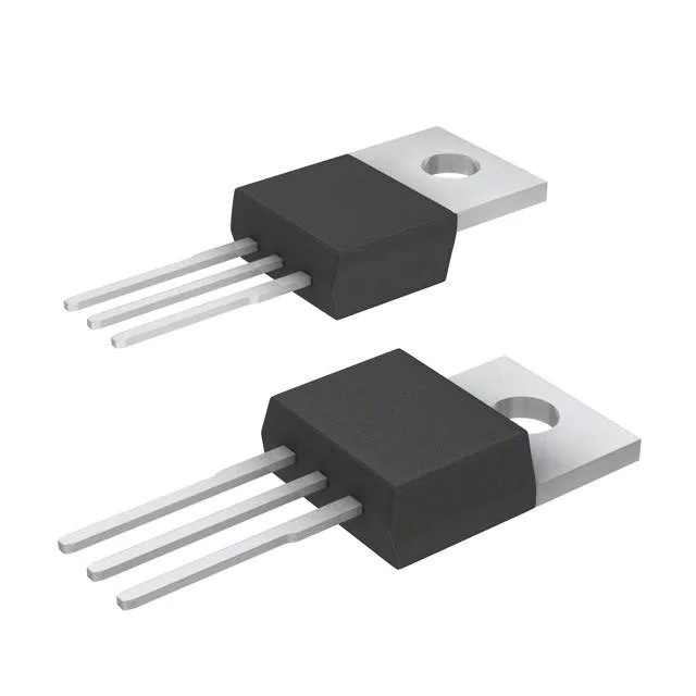
Infineon Technologies IPP65R310CFDXKSA2

IPP65R310CFDXKSA2 CoolMOS™ N-Ch 650V 11.4A TO-220-3

MPNIPP65R310CFDXKSA2
End of Life

Infineon CoolMOS™ CFD2, N-Channel MOSFET, 650 V drain-source, 11.4 A continuous drain at 25°C case, 310 mOhm Rds(on) at 10 V gate drive, 41 nC gate charge, TO-220-3 through-hole package, -55°C to 150°C junction temperature.

$2.68Ref. price · indicative, final on quote
PackagingTO-220-3
StockContact for availability
MOQ1 pcs
  • 100% new & originalTraceable channels only — no refurbs, no pulls, no remarked parts.
  • Date & lot codes on quoteStated per line before you commit; label photos on request.
  • MSL-compliant ESD packingMoisture-sealed bags with indicator cards; reels photo-verified.
  • PayPal buyer protectionPay by T/T, PayPal or Payoneer — card payments covered end to end.

Specifications

IPP65R310CFDXKSA2 Technical Specifications
ParameterValue
SeriesCoolMOS™ CFD2
FET typeN-Channel
Mounting typeThrough Hole
Drain to source voltage650 V
Drive voltage (Max rds on, min rds on)10V
Current - continuous drain (Id) @ 25°C11.4A (Tc)
Power dissipation104.2W (Tc)
Operating temperature-55°C ~ 150°C (TJ)
PackageTube
Vgs±20V
TechnologyMOSFET (Metal Oxide)
CaseTO-220-3
Vgs(th) (Max) @ id4.5V @ 400µA
Rds on (Max) @ id, vgs310mOhm @ 4.4A, 10V
Gate charge (Qg) (Max) @ vgs41 nC @ 10 V
Input capacitance (Ciss) (Max) @ vds1100 pF @ 100 V

Product details

650 V CoolMOS™ CFD2 — the voltage-class anchor for 400 V bus designs

The Infineon IPP65R310CFDXKSA2 is an N-channel CoolMOS™ CFD2 MOSFET rated for 650 V drain-source breakdown, which gives you a solid 250 V of derating headroom above a typical 400 V DC bus in power-factor-correction stages or flyback converters.

The total gate charge at 10 V is 41 nC, which is a mid-range figure for a 650 V MOSFET in this current class. At a 100 kHz switching frequency, the average gate drive current needed is Qg × f = 4.1 mA — well within what a standard gate driver IC can source. The 1100 pF input capacitance at 100 V drain-source gives you a handle on the switching speed: the driver must charge and discharge this capacitance through the gate resistor to set the turn-on and turn-off slew rates.

Through-hole TO-220 — heatsink-friendly, hand-solderable

The PG-TO220-3 package is the classic three-lead through-hole power package. The metal tab is the drain connection, and the mounting hole accepts a standard TO-220 screw or clip to a heatsink.

Full military temperature span — industrial and outdoor power

The 150°C maximum junction temperature gives the thermal designer headroom to push the part to its rated 11.4 A continuous drain current at elevated ambient temperatures, as long as the case-to-heatsink thermal resistance is managed.

Threshold voltage and drive logic — 4.5 V max at 400 µA

The maximum gate threshold voltage is 4.5 V at 400 µA drain current, which means a standard 10 V gate drive is needed to achieve the rated 310 mOhm on-resistance.

Frequently asked questions

What is the typical gate charge of IPP65R310CFDXKSA2?

The maximum gate charge at 10 V gate-source voltage is 41 nC. This is the total charge needed to switch the MOSFET from off to fully on at that drive voltage, and it determines the average gate drive current at the target switching frequency.

Is IPP65R310CFDXKSA2 RoHS compliant?

Yes, the IPP65R310CFDXKSA2 is ROHS3 compliant, meeting the latest EU restriction of hazardous substances directive without any exemptions.