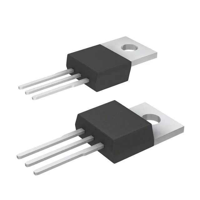
Infineon Technologies IPP60R060C7XKSA1

IPP60R060C7XKSA1 CoolMOS™ C7 N-Channel MOSFET, 600 V, 35 A

MPNIPP60R060C7XKSA1
End of Life

Infineon CoolMOS™ C7 series, IPP60R060C7XKSA1, N-Channel MOSFET, 600 V Vdss, 35 A Id, 60 mOhm Rds(on) at 10 V, 68 nC Qg, -55 to 150 °C, PG-TO220-3, Through Hole.

$8.24Ref. price · indicative, final on quote
PackagingTO-220-3
StockContact for availability
MOQ1 pcs
  • 100% new & originalTraceable channels only — no refurbs, no pulls, no remarked parts.
  • Date & lot codes on quoteStated per line before you commit; label photos on request.
  • MSL-compliant ESD packingMoisture-sealed bags with indicator cards; reels photo-verified.
  • PayPal buyer protectionPay by T/T, PayPal or Payoneer — card payments covered end to end.

Specifications

IPP60R060C7XKSA1 Technical Specifications
ParameterValue
SeriesCoolMOS™ C7
FET typeN-Channel
Mounting typeThrough Hole
Drain to source voltage600 V
Drive voltage (Max rds on, min rds on)10V
Current - continuous drain (Id) @ 25°C35A (Tc)
Power dissipation162W (Tc)
Operating temperature-55°C ~ 150°C (TJ)
PackageTube
Vgs±20V
TechnologyMOSFET (Metal Oxide)
CaseTO-220-3
Vgs(th) (Max) @ id4V @ 800µA
Rds on (Max) @ id, vgs60mOhm @ 15.9A, 10V
Gate charge (Qg) (Max) @ vgs68 nC @ 10 V
Input capacitance (Ciss) (Max) @ vds2850 pF @ 400 V

Product details

600 V, 35 A N-channel in a TO-220 — the workhorse PFC switch

The IPP60R060C7XKSA1: This is the part you reach for when a boost PFC stage, an LLC half-bridge, or a flyback primary switch needs a through-hole TO-220-3 package that can be bolted to a heatsink and dissipate 162 W at the case. The 68 nC total gate charge at 10 V is moderate for this voltage class.

Drain-source voltage is rated 600 V. Input capacitance Ciss is 2850 pF at 400 V drain-source — that's the Miller plateau charge the driver must push through during the switching transition. The 68 nC Qg total at 10 V means a driver sourcing 1 A can turn the FET on in about 68 ns, which is fast enough for 100 kHz hard-switching without excessive ringing if the gate loop inductance is kept under 10 nH. Gate threshold voltage is specified at 4 V maximum with 800 µA drain current — a standard 10 V gate drive saturates the channel fully, pulling Rds(on) to its rated minimum. The ±20 V maximum gate-source rating gives margin for overshoot on a 12 V or 15 V gate drive rail.

The TO-220-3 package is a standard through-hole form factor that stores well on the shelf; no special dry-pack requirements beyond the normal anti-static bag. ROHS3 compliance is confirmed, which keeps it compatible with lead-free assembly processes and avoids the restricted-substance compliance checks that older parts sometimes trigger.

Where it fits — power conversion and industrial drives

The 600 V / 35 A rating with 60 mOhm Rds(on) places this MOSFET squarely in the sweet spot for 1–3 kW offline power supplies: boost PFC stages, two-switch forward converters, and LLC resonant half-bridges. The through-hole TO-220-3 package with a metal tab means you can bolt it to a chassis or heatsink with a thermal pad or mica insulator — the 162 W power dissipation rating assumes the case is held at 25 °C, so the actual heatsink must be sized to keep the case temperature below about 110 °C at full load.

Frequently asked questions

What is the Rds(on) of the IPP60R060C7XKSA1?

This is the value used for conduction-loss calculations in the power stage.

What is the gate charge and what does it mean for switching frequency?

Total gate charge is 68 nC at a 10 V gate drive. For a 100 kHz switching frequency, the average gate-drive current required is about 6.8 mA — well within the capability of most dedicated MOSFET drivers. The 2850 pF input capacitance at 400 V drain-source also contributes to the switching loss, so the total gate-drive power is roughly Qg × Vgs × fsw.