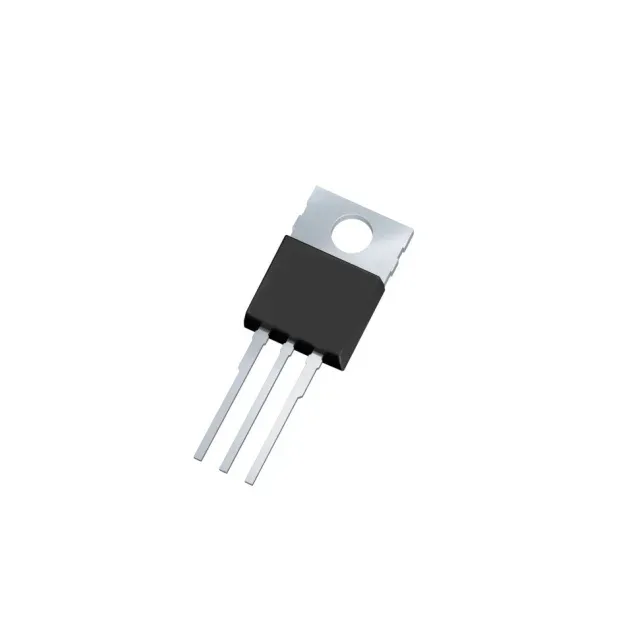
The IPP120P04P4L03AKSA2: P-channel construction means the load connects to the drain and the source ties to the positive rail, eliminating the need for a charge-pump or bootstrap circuit in high-side applications. The trade-off historically has been higher Rds(on) versus an equivalent N-channel, but at 3.4 mOhm this part closes that gap to within a few milliohms of comparable N-channel parts in the same package.
234 nC gate charge — sizing the gate driver for the switching frequency
Total gate charge is 234 nC at a 10 V gate drive. At 4.5 V the on-resistance will be higher than the 3.4 mOhm maximum specified at 10 V — the datasheet curve should be consulted for the exact derating. For designs running from a 5 V rail, budget additional margin in the thermal calculation.