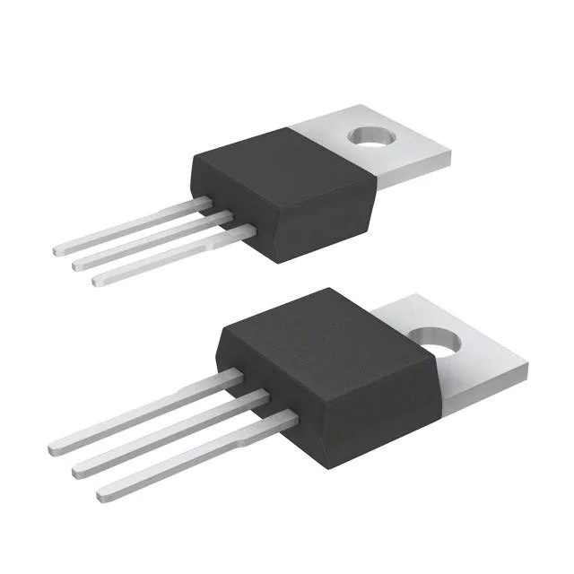
Infineon Technologies IPP020N06NAKSA1

Infineon IPP020N06NAKSA1 OptiMOS N-Channel MOSFET

MPNIPP020N06NAKSA1
End of Life

Infineon OptiMOS N-Channel MOSFET, IPP020N06NAKSA1, 60 V Vdss, 29 A (Ta) / 120 A (Tc), 2 mOhm Rds(on) at 10 V, 106 nC gate charge, TO-220-3, -55 to 175 °C junction.

$4.4Ref. price · indicative, final on quote
PackagingTO-220-3
RoHSROHS3 Compliant
SeriesOptiMOS™
Independent supplier — new & surplus stockAuthenticity-screened · ESD-safe packingListing updated Jul 2026

Specifications

IPP020N06NAKSA1 specifications
ParameterValue
SeriesOptiMOS™
FET typeN-Channel
MountingThrough Hole
Drain to source voltage60 V
Drive voltage (Max rds on, min rds on)6V, 10V
Current - continuous drain (Id) @ 25°C29A (Ta), 120A (Tc)
Power dissipation3W (Ta), 214W (Tc)
Operating temperature-55°C ~ 175°C (TJ)
PackageTube
Vgs±20V
TechnologyMOSFET (Metal Oxide)
CaseTO-220-3
Vgs(th) (Max) @ id2.8V @ 143µA
Rds on (Max) @ id, vgs2mOhm @ 100A, 10V
Gate charge (Qg) (Max) @ vgs106 nC @ 10 V
Input capacitance (Ciss) (Max) @ vds7800 pF @ 30 V

Product details

What the 2 mOhm Rds(on) means for the switching node

Current rating — the package-limited vs die-limited split

The dual current spec — 29 A at ambient (Ta) versus 120 A at case temperature (Tc) — is the first thing to reconcile on the BOM.

Drive voltage range is 6 V to 10 V for minimum and maximum Rds(on). The 2 mOhm figure is specified at 10 V.

ROHS3 compliance is confirmed.

Frequently asked questions

What is the Rds(on) of IPP020N06NAKSA1 at 10V gate drive?

The maximum Rds(on) is 2 mOhm at 100 A drain current with 10 V applied to the gate. This is the rated condition; the on-resistance will be higher at lower gate voltages or lower currents, so check the typical curve in the datasheet for your operating point.

Is IPP020N06NAKSA1 RoHS compliant?

Yes, the part is ROHS3 compliant per Infineon's classification.

Can IPP020N06NAKSA1 replace a failed IRFZ44 or similar legacy MOSFET?

The IPP020N06NAKSA1 has a lower Rds(on) (2 mOhm vs approximately 17.5 mOhm for IRFZ44) and higher current rating (120 A vs 49 A) in the same TO-220 footprint. Gate drive requirements differ — the OptiMOS part needs 10 V for full enhancement versus the IRFZ44's 10 V as well, so the drive circuit is compatible. The higher gate charge (106 nC vs roughly 60 nC for IRFZ44) means the gate driver must supply more current to maintain the same switching speed. Check the switching loss budget before substituting.