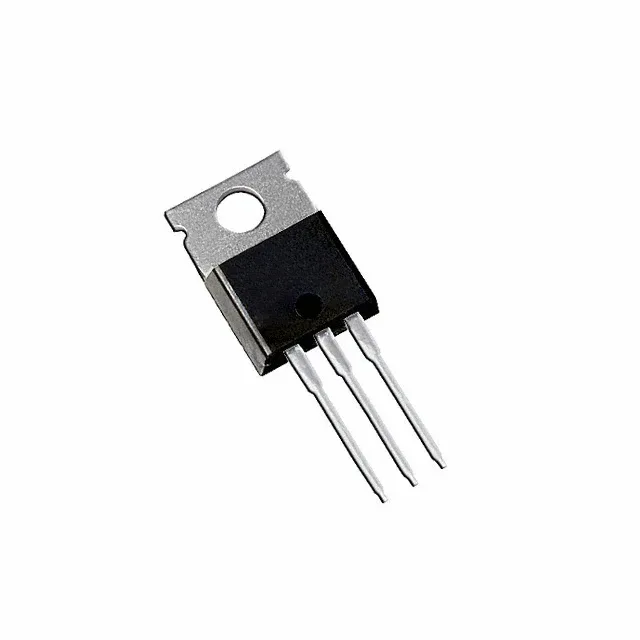
Infineon Technologies IPP019N06NF2SAKMA1 — Logic ICs

Infineon IPP019N06NF2SAKMA1 N-Channel MOSFET, 60 V, 1.9 mOhm

MPNIPP019N06NF2SAKMA1
End of Life

Infineon StrongIRFET™ IPP019N06NF2SAKMA1, N-Channel MOSFET, 60 V Vdss, 1.9 mOhm Rds(on) @ 100 A, 162 nC gate charge, TO-220-3, -55°C to 175°C.

$2.31Ref. price · indicative, final on quote
PackagingTO-220-3
StockContact for availability
MOQ1 pcs
  • 100% new & originalTraceable channels only — no refurbs, no pulls, no remarked parts.
  • Date & lot codes on quoteStated per line before you commit; label photos on request.
  • MSL-compliant ESD packingMoisture-sealed bags with indicator cards; reels photo-verified.
  • PayPal buyer protectionPay by T/T, PayPal or Payoneer — card payments covered end to end.

Specifications

IPP019N06NF2SAKMA1 Technical Specifications
ParameterValue
SeriesStrongIRFET™
FET typeN-Channel
Mounting typeThrough Hole
Drain to source voltage60 V
Drive voltage (Max rds on, min rds on)6V, 10V
Current - continuous drain (Id) @ 25°C33A (Ta), 185A (Tc)
Power dissipation3.8W (Ta), 188W (Tc)
Operating temperature-55°C ~ 175°C (TJ)
PackageTube
Vgs±20V
TechnologyMOSFET (Metal Oxide)
CaseTO-220-3
Vgs(th) (Max) @ id3.3V @ 129µA
Rds on (Max) @ id, vgs1.9mOhm @ 100A, 10V
Gate charge (Qg) (Max) @ vgs162 nC @ 10 V
Input capacitance (Ciss) (Max) @ vds7300 pF @ 30 V

Product details

A 1.9 mOhm switch for 60 V rails — sizing the loss budget

Its headline figure is a maximum on-resistance of 1.9 mOhm at 100 A drain current with 10 V gate drive — that is the number that determines conduction loss in a high-current path like an OR-ing diode replacement, a motor-drive H-bridge, or a synchronous rectifier stage.

185 A continuous — what the package and temperature grade allow

The continuous drain current is rated 185 A when the case temperature is held at 25°C, and 33 A when the ambient air is 25°C with no heatsink. That gap is the thermal reality: the TO-220-3 package (PG-TO220-3-U05) can pass the current if the junction stays under 175°C, but the 3.8 W ambient dissipation limit means you need a heatsink for any load above a few amps.

Gate drive and input capacitance — what the 6 V / 10 V spec means

The drive voltage range is specified as 6 V minimum for the lowest Rds(on) and 10 V for the rated maximum performance. At 10 V the 1.9 mOhm figure is guaranteed; if your gate drive rail is 5 V or 3.3 V, the on-resistance will be higher — check the typical curves in the datasheet. The 7300 pF input capacitance at 30 V drain bias is moderate for a 60 V device of this current class; it loads the gate driver with about 162 nC per switching event, so a driver capable of sourcing at least 2 A peak is a safe starting point for keeping switching times under 100 ns.

Frequently asked questions

What is the Rds(on) and gate charge of IPP019N06NF2SAKMA1?

The maximum gate charge is 162 nC at 10 V. These two numbers together let you calculate conduction loss and switching loss for your operating point.