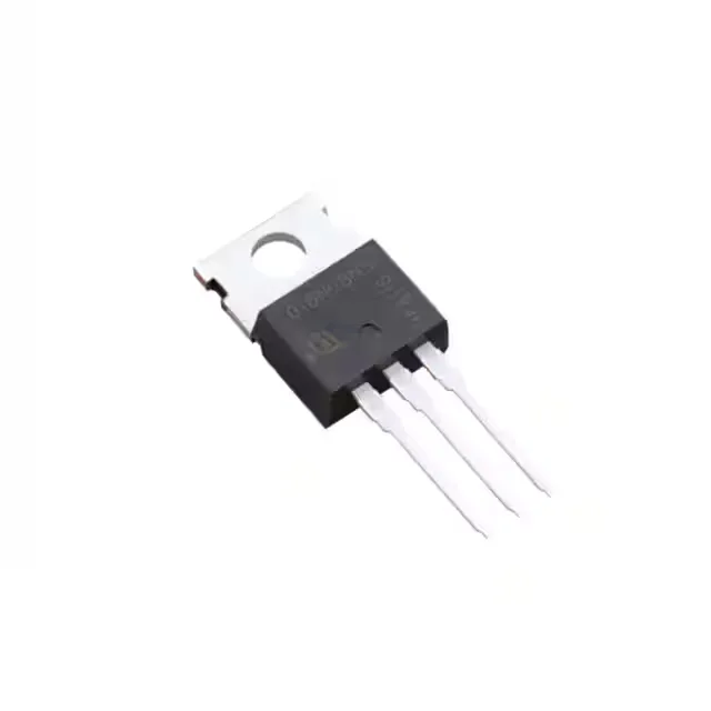
80 V, 1.6 mΩ — the conduction-loss story
The Infineon IPP016N08NF2SAKMA1 is an N-channel MOSFET from the StrongIRFET™ 2 family, built on a trench technology rated for 40 to 100 V. Its headline figure is a maximum Rds(on) of 1.6 mΩ at a 10 V gate drive with 100 A of drain current — a number that tells you the conduction loss at full load will be under 16 W before thermal derating. The 80 V drain-to-source rating places it in the sweet spot for 48 V telecom rectifiers, 24 V automotive systems, and battery-management contactor circuits where the rail sees transients above 60 V.
Current rating — package versus die
Two continuous-drain figures are listed: 35 A at 25 °C when the case is at ambient (Ta), and 196 A at 25 °C when the case is held at 25 °C (Tc). The 35 A Ta number is what you size the PCB copper and airflow for in a real enclosure; the 196 A Tc number tells you what the die can pass if you bolt the TO-220-3 tab to a heatsink with forced air or liquid cooling. The package's rated power dissipation is 300 W at Tc and 3.8 W at Ta — a 78:1 ratio that makes the thermal interface the deciding factor in any high-current design.
The gate charge is 255 nC at a 10 V gate drive, which is substantial — expect the gate driver to supply several amperes peak if you need fast turn-on for hard-switching at 50 kHz or above. The input capacitance is 12000 pF at 40 V drain bias, and the threshold voltage maximum is 3.8 V at 267 µA. The drive voltage range for achieving the minimum and maximum Rds(on) is 6 V to 10 V, meaning a 5 V logic-level gate signal will not fully enhance the channel; the part is designed for a 10 V gate rail, or at least 6 V, to hit the rated on-resistance.
The junction temperature range is -55 to 175 °C, which covers military and automotive under-hood environments. The 175 °C max junction allows the die to run hot in a sealed enclosure or near an engine block, but the 300 W Tc dissipation rating assumes the case stays at 25 °C — in practice, derate the power linearly above 25 °C case temperature. The ±20 V maximum gate-to-source rating is standard for this voltage class.
The IPP016N08NF2SAKMA1 comes in a PG-TO220-3 through-hole package — the standard three-lead TO-220 with a metal tab for screw-mount or clip heatsinking. Through-hole mounting is preferred for high-power designs where the leads carry the full drain current and the tab needs a thermal path to the chassis or heatsink.