1.5 mOhm Rds(on) — what it costs at 100°C junction
At a typical 125°C junction, expect that on-resistance to nearly double, which is the real conduction loss the thermal design must budget for.
Total gate charge Qg is 250 nC at 10 V. The 20000 pF input capacitance at 20 V Vds tells you the driver sees a substantial capacitive load on each switching edge.
175°C junction — thermal headroom for high-current designs
Rated operating junction temperature from -55°C to 175°C gives 25°C more margin than the common 150°C ceiling. In a 120 A continuous application, that extra headroom translates to either a smaller heatsink or higher ambient tolerance before derating. Power dissipation is rated at 250 W at case temperature — a number that assumes an infinite heatsink, so real-world derating must follow the datasheet's thermal resistance curve.
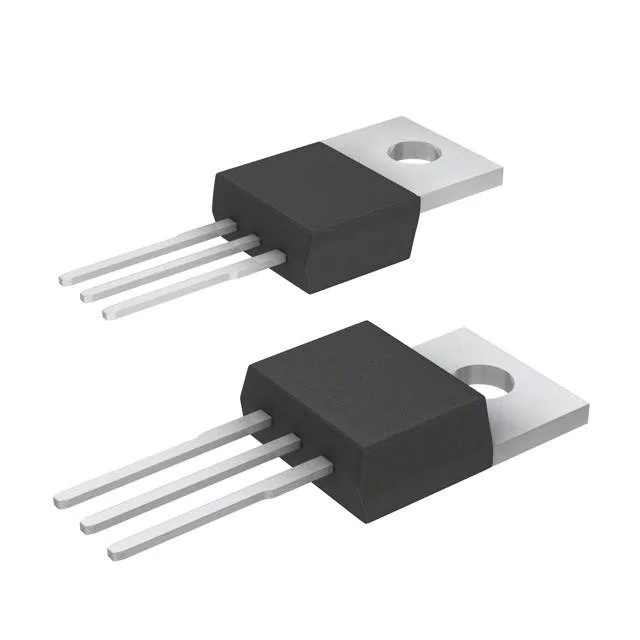
Through-hole TO-220 — the workhorse package
Housed in a standard TO-220-3 (PG-TO220-3-1) with through-hole mounting. The tab is the drain. No MSL concerns — the leadframe is plated for soldering into a PCB or bolted to a heatsink.