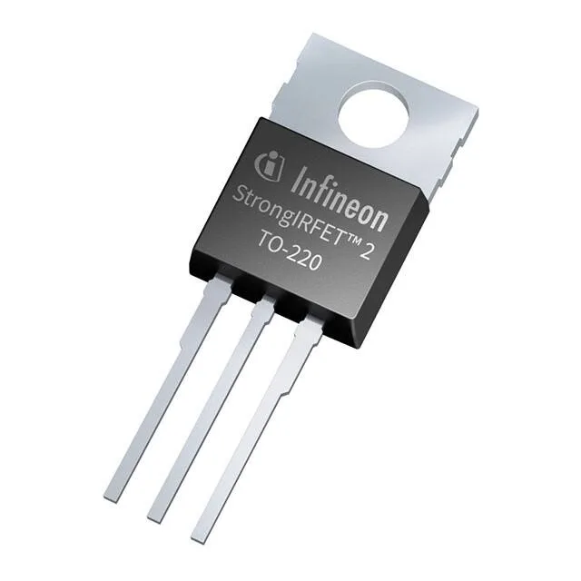
Infineon Technologies IPP014N06NF2SAKMA2 — Logic ICs

Infineon IPP014N06NF2SAKMA2 StrongIRFET N-Ch 60V 1.4mOhm

MPNIPP014N06NF2SAKMA2
End of Life

Infineon StrongIRFET™ series, IPP014N06NF2SAKMA2, N-Channel MOSFET, 60 V Vdss, 1.4 mOhm Rds(on) @ 100 A, 10 V, 198 A continuous drain (Tc), PG-TO220-3-U05 through-hole package, -55°C to 175°C junction temperature.

$3.86Ref. price · indicative, final on quote
PackagingTO-220-3
StockContact for availability
MOQ1 pcs
  • 100% new & originalTraceable channels only — no refurbs, no pulls, no remarked parts.
  • Date & lot codes on quoteStated per line before you commit; label photos on request.
  • MSL-compliant ESD packingMoisture-sealed bags with indicator cards; reels photo-verified.
  • PayPal buyer protectionPay by T/T, PayPal or Payoneer — card payments covered end to end.

Specifications

IPP014N06NF2SAKMA2 Technical Specifications
ParameterValue
SeriesStrongIRFET™
FET typeN-Channel
Mounting typeThrough Hole
Drain to source voltage60 V
Drive voltage (Max rds on, min rds on)6V, 10V
Current - continuous drain (Id) @ 25°C39A (Ta), 198A (Tc)
Power dissipation3.8W (Ta), 300W (Tc)
Operating temperature-55°C ~ 175°C (TJ)
PackageTube
Vgs±20V
TechnologyMOSFET (Metal Oxide)
CaseTO-220-3
Vgs(th) (Max) @ id3.3V @ 246µA
Rds on (Max) @ id, vgs1.4mOhm @ 100A, 10V
Gate charge (Qg) (Max) @ vgs305 nC @ 10 V
Input capacitance (Ciss) (Max) @ vds13800 pF @ 30 V

Product details

1.4 mOhm at 10 V — the conduction-loss anchor

The Infineon IPP014N06NF2SAKMA2 is a 60 V N-channel MOSFET from the StrongIRFET™ family, built on a trench technology rated for 40 to 100 V applications. The 305 nC typical gate charge at 10 V means the gate driver needs to source and sink substantial current for fast switching edges; pair it with a driver rated for at least 2 A peak to keep transition times in the tens of nanoseconds. The 13800 pF input capacitance at 30 V Vds reinforces that the driver sees a heavy capacitive load.

198 A continuous, 300 W dissipation — thermal design rules

The 198 A continuous drain current at case temperature (Tc) and 300 W maximum power dissipation at Tc assume an infinite heatsink — in practice, the junction-to-case thermal path through the TO-220 tab determines the real limit. The 39 A at 25°C ambient (Ta) with no heatsink is the bare-device ceiling; a forced-air or liquid-cooled heatsink is needed to approach the 198 A figure.

PG-TO220-3-U05 — mounting and footprint

The through-hole PG-TO220-3-U05 package has the standard three-lead TO-220 footprint with a metal tab for heatsink attachment. The U05 suffix indicates a specific lead form for automated insertion equipment. The tab is electrically connected to the drain — an insulating pad or thermal compound is required when mounting to a grounded heatsink. The 3.8 W (Ta) and 300 W (Tc) dissipation ratings bracket the thermal design space: the lower figure is the bare-board limit, the upper figure is what a well-ventilated heatsink assembly can achieve.

Active lifecycle, ROHS3, and sourcing posture

ROHS3 compliant covers the full restricted-substance list including the four phthalates, clearing it for EU-market and most OEM environmental requirements.

Frequently asked questions

Is IPP014N06NF2SAKMA2 RoHS compliant?

Yes, it is ROHS3 compliant, covering the latest restricted substances including the four phthalates.