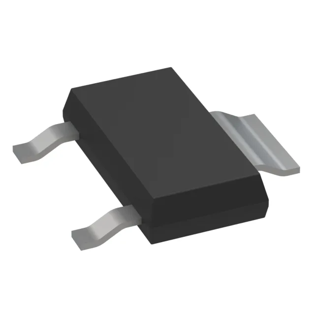
500 V, 4.8 A CoolMOS CE in a compact SOT223
It packs a 1.4 Ohm maximum on-resistance — specified at 900 mA drain current with 13 V gate drive — into the PG-SOT223-3 surface-mount footprint.
The 1.4 Ohm Rds(on) at 13 V gate drive is the figure to use for conduction-loss calculations at the nominal operating point. At 900 mA, that is about 1.1 W of conduction loss — well within the 5 W package limit, but the junction temperature rise will cut into that margin as ambient climbs. The total gate charge of 8.2 nC at 10 V means a modest gate driver can switch this FET at 100 kHz with under 1 mA average drive current; switching losses stay low enough for most flyback and single-switch forward topologies. Input capacitance is 178 pF at 100 V drain bias — a light load on the driver, and the Miller plateau will be short, which helps keep the turn-on and turn-off delays in the tens of nanoseconds range. For a 100 kHz hard-switched design, the crossover losses will be dominated by the output capacitance (Coss) rather than the gate charge, so plan for a snubber or a valley-switching controller if efficiency targets are tight.
Package thermal reality — SOT223 at 5 W
The PG-SOT223-3 package is rated for 5 W total power dissipation at the case. That is a firm ceiling — the copper pad area on the PCB under the drain tab sets the actual thermal resistance. For continuous operation at 4.8 A, the conduction loss alone will push past 5 W unless the Rds(on) is de-rated for temperature (it roughly doubles at 150°C junction). In practice, this part is run at 1-2 A continuous with good PCB heatsinking, or used in pulsed applications like inrush limiting. The 150°C ceiling is a hard stop — the plastic SOT223 will not survive sustained operation above that, and the solder joints fatigue faster at the high end of the range.
Infineon continues to manufacture the CoolMOS CE series in the SOT223 package. No known PCN on this specific variant; the date-code and marking traceability back to Infineon's fabs is clean through the authorized channel.