4.6 mOhm Rds(on) at 90 A — the conduction-loss floor
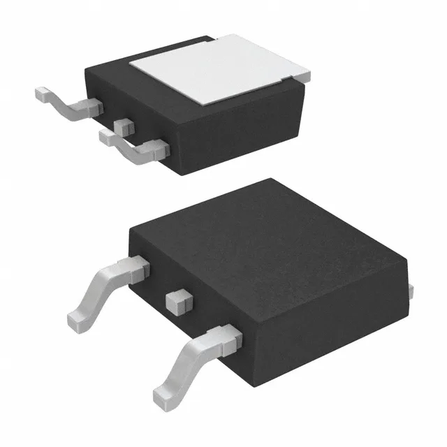
At 90 A, I²R loss is roughly 37 W, which must be managed through the PG-TO252-3-11 package's exposed tab and the PCB copper area.
Automotive qualification and temperature envelope
AEC-Q101 qualified, the IPD90N06S4L05ATMA2 is released for automotive stress and reliability screening. The 175 °C TJ ceiling gives headroom for self-heating at high continuous current without entering the derating zone.
Gate charge and drive requirements
Total gate charge is 110 nC at 10 V, with a maximum gate-source voltage of ±16 V.
It is ROHS3 compliant. No official second-source cross-reference is listed, so the BOM relies on this single Infineon order code for the position.
PG-TO252-3-11 footprint and thermal management
The maximum power dissipation is 107 W at the case temperature — achieving that requires a low thermal resistance path through the PCB to ambient, typically a 1 oz or 2 oz copper pour on the drain node.