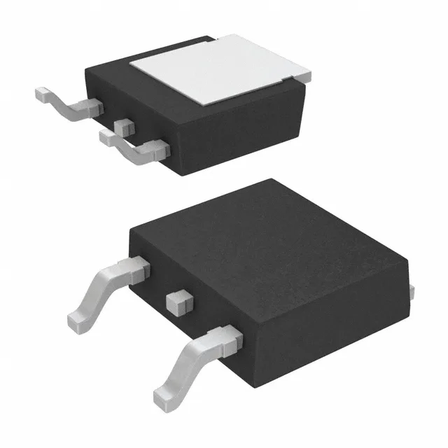
Infineon Technologies IPD80R2K7C3AATMA1

Infineon IPD80R2K7C3AATMA1 CoolMOS N-Ch MOSFET, 800 V, 2 A

MPNIPD80R2K7C3AATMA1
End of Life

Infineon CoolMOS™ IPD80R2K7C3AATMA1, N-channel MOSFET, 800 V Vdss, 2 A Id, 2.7 Ohm Rds(on) at 10 V, AEC-Q101 qualified, D-Pak (TO-252) surface mount.

$1.62Ref. price · indicative, final on quote
PackagingTO-252-3, DPak (2 Leads + Tab), SC-63
StockContact for availability
MOQ1 pcs
  • 100% new & originalTraceable channels only — no refurbs, no pulls, no remarked parts.
  • Date & lot codes on quoteStated per line before you commit; label photos on request.
  • MSL-compliant ESD packingMoisture-sealed bags with indicator cards; reels photo-verified.
  • PayPal buyer protectionPay by T/T, PayPal or Payoneer — card payments covered end to end.

Specifications

IPD80R2K7C3AATMA1 Technical Specifications
ParameterValue
SeriesCoolMOS™
FET typeN-Channel
Mounting typeSurface Mount
Drain to source voltage800 V
Drive voltage (Max rds on, min rds on)10V
Current - continuous drain (Id) @ 25°C2A (Tc)
Power dissipation42W (Tc)
Operating temperature-40°C ~ 150°C (TJ)
GradeAutomotive
PackageTape & Reel (TR); Cut Tape (CT)
Vgs±20V
TechnologyMOSFET (Metal Oxide)
QualificationAEC-Q101
CaseTO-252-3, DPak (2 Leads + Tab), SC-63
Vgs(th) (Max) @ id3.9V @ 250µA
Rds on (Max) @ id, vgs2.7Ohm @ 1.2A, 10V
Gate charge (Qg) (Max) @ vgs1.5 nC @ 10 V
Input capacitance (Ciss) (Max) @ vds290 pF @ 100 V

Product details

AEC-Q101 and 150°C junction — built for under-hood

That 150°C ceiling is the real differentiator for engine-bay or transmission-mounted electronics — the part keeps its rated SOA when ambient air hits 105°C and the PCB is radiating heat from nearby power stages.

Gate charge and switching speed — what 1.5 nC means

Total gate charge is 1.5 nC at 10 V, and input capacitance (Ciss) is 290 pF at 100 V. For a 100 kHz hard-switched converter, the gate-drive power is roughly Qg × Vgs × fsw — about 1.5 mW. That is negligible, so the driver IC stays cool and the switching edge is fast enough to keep cross-conduction losses low. The trade-off is the 2.7 Ohm Rds(on): this is not a part for a 10 A boost stage; it is sized for the 0.5 A to 1.5 A auxiliary rail where the 800 V rating buys you headroom against bus transients.

D-Pak (TO-252) — board area and thermal path

Surface-mount D-Pak (TO-252) with the tab as the drain connection. The 42 W power dissipation at case temperature assumes a copper area on the PCB that sinks heat from the tab — a 25 mm × 25 mm pad on a 2 oz copper board is the typical starting point. The tab is electrically live (drain), so the thermal vias must be isolated from ground unless the design uses the drain as the output node.

ROHS3 compliant.

Frequently asked questions

What is the difference between IPD80R2K7C3AATMA1 and IPD50R950CEAUMA1?

The IPD50R950CEAUMA1 is a 500 V device with 950 mOhm Rds(on) and 4.3 A continuous rating, versus the 800 V / 2.7 Ohm / 2 A of the IPD80R2K7C3AATMA1. The 800 V part is the right choice when the DC bus exceeds 400 V or when you need margin against 600 V transients. The 500 V part handles more current in a lower-voltage rail. They are not pin-compatible substitutes — the gate drive and thermal design differ.

What compliance documentation is available for IPD80R2K7C3AATMA1?

The part is ROHS3 compliant. Infineon provides the standard AEC-Q101 qualification report and RoHS declaration. No UL or IEC certification is listed in the product record.