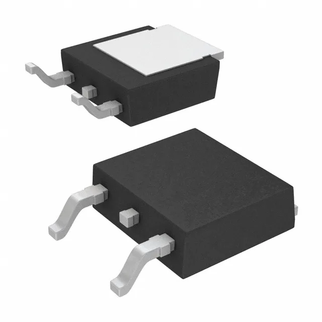
The IPD80R2K4P7ATMA1: The 2.4 Ohm maximum on-resistance at 800 mA and 10 V gate drive means at 1 A drain current the conduction loss is about 2.4 W — within the 22 W power dissipation limit at case temperature, but the junction will climb quickly if the TO-252 pad isn't soldered to a decent copper area. The 7.5 nC total gate charge is low enough that a 100 mA gate-drive source can switch the FET in under 100 ns, which matters when you're pushing the switching frequency above 100 kHz in a compact flyback. Input capacitance is 150 pF at 500 V drain-source — that's a small number that keeps the Miller plateau short and the switching losses low.
Active production, ROHS3, and the TO-252 footprint
The TO-252-3 (DPak) package has a single exposed tab (the drain) that must be soldered to the PCB copper pour for thermal management; the junction-to-case thermal path is the limiting factor for power dissipation, not the plastic body.