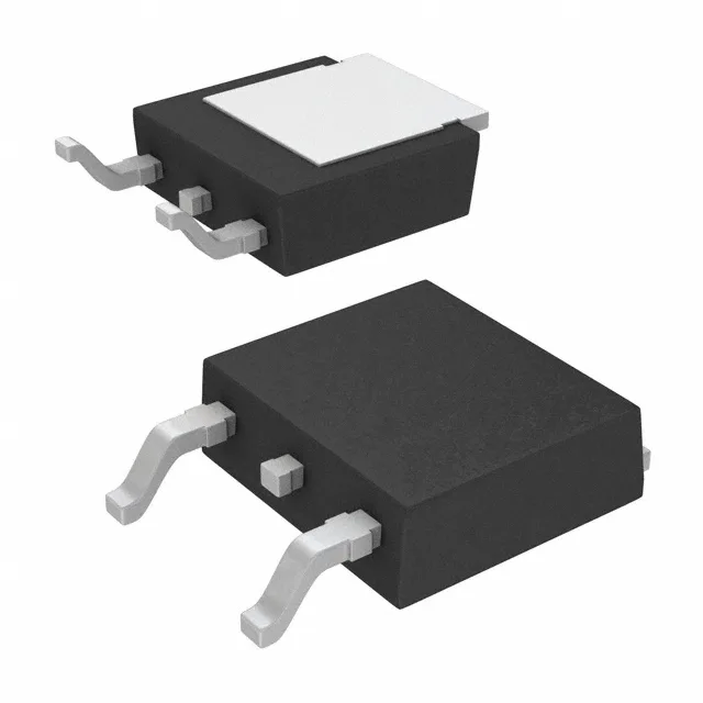
Infineon Technologies IPD70R600P7SAUMA1

IPD70R600P7SAUMA1 CoolMOS P7 N-Ch MOSFET, 700 V, 8.5 A

MPNIPD70R600P7SAUMA1
End of Life

Infineon CoolMOS™ P7, IPD70R600P7SAUMA1, N-Channel MOSFET, 700 Vdss, 8.5 A Id, 600 mOhm Rds(on) @ 1.8 A 10 V, 10.5 nC gate charge, PG-TO252-3 package, -40 to 150 °C TJ.

$0.86Ref. price · indicative, final on quote
PackagingTO-252-3, DPak (2 Leads + Tab), SC-63
StockContact for availability
MOQ1 pcs
  • 100% new & originalTraceable channels only — no refurbs, no pulls, no remarked parts.
  • Date & lot codes on quoteStated per line before you commit; label photos on request.
  • MSL-compliant ESD packingMoisture-sealed bags with indicator cards; reels photo-verified.
  • PayPal buyer protectionPay by T/T, PayPal or Payoneer — card payments covered end to end.

Specifications

IPD70R600P7SAUMA1 Technical Specifications
ParameterValue
SeriesCoolMOS™ P7
FET typeN-Channel
Mounting typeSurface Mount
Drain to source voltage700 V
Drive voltage (Max rds on, min rds on)10V
Current - continuous drain (Id) @ 25°C8.5A (Tc)
Power dissipation43W (Tc)
Operating temperature-40°C ~ 150°C (TJ)
PackageTape & Reel (TR); Cut Tape (CT)
Vgs±16V
TechnologyMOSFET (Metal Oxide)
CaseTO-252-3, DPak (2 Leads + Tab), SC-63
Vgs(th) (Max) @ id3.5V @ 90µA
Rds on (Max) @ id, vgs600mOhm @ 1.8A, 10V
Gate charge (Qg) (Max) @ vgs10.5 nC @ 10 V
Input capacitance (Ciss) (Max) @ vds364 pF @ 400 V

Product details

The junction temperature range spans -40 to 150 °C.

ROHS3 compliance is confirmed, so the part meets the current restricted-substance requirements for EU and most global markets.

PG-TO252-3 footprint — surface-mount assembly with a thermal tab

The datasheet's 43 W maximum power dissipation at case temperature assumes a low-thermal-resistance board footprint, not free-air convection. For prototype or small-batch builds, Cut Tape is the practical option.

How this compares to the IPD50R950CEAUMA1

The IPD70R600P7SAUMA1 has a 700 V drain-source breakdown voltage and 600 mOhm on-resistance at 1.8 A, 10 V. A board originally laid out for the 500 V CE part will accept the 700 V P7 part electrically and physically — same package, same pinout — but the gate-drive circuit must supply a clean 10 V rail to hit the rated Rds(on). If the existing driver was tuned for the CE's 13 V plateau, the P7 will still switch but with a higher on-resistance than the datasheet maximum.

Frequently asked questions

Will IPD70R600P7SAUMA1 drop into a board designed for IPD50R950CEAUMA1?

Physically yes — both are PG-TO252-3 (DPAK) with the same footprint and pinout. Electrically the 700 V P7 part has a higher breakdown voltage and lower on-resistance than the 500 V CE sibling. The main caveat is gate drive: the P7 specifies Rds(on) at 10 V, while the CE part uses 13 V. If your existing driver delivers a clean 10 V rail, the swap works; if it was tuned for 13 V, expect higher on-resistance than the datasheet max.