P-channel load switch for 60V rails
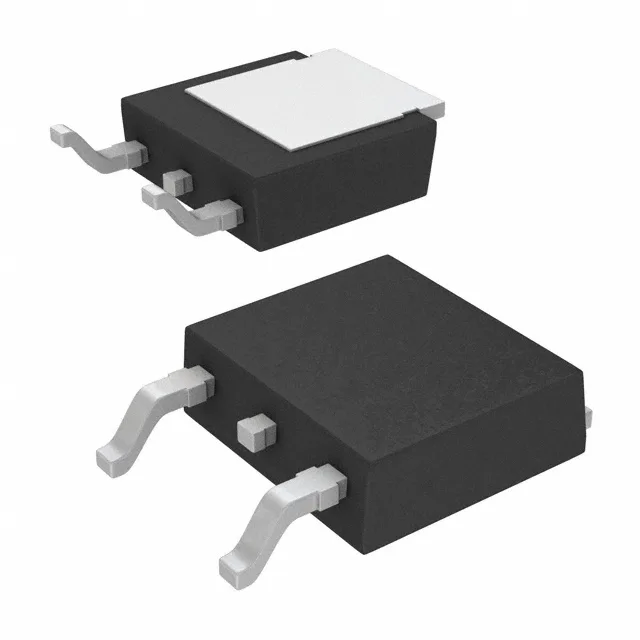
It comes in a TO-252-3 (DPak) surface-mount package with the PG-TO252-3-313 supplier code. P-channel devices simplify high-side switching by eliminating the need for a charge-pump gate driver — the source connects to the positive rail and the gate is pulled low to turn on.
On-resistance and gate charge — the switching loss trade-off
The 39 nC total gate charge at 10 V tells you the gate-driver current needed: a 1 A driver charges the gate in roughly 39 ns, but a 100 mA logic-level driver will stretch the switching edge and increase crossover loss. Input capacitance Ciss is 1600 pF at 30 V drain-source. That is moderate for a 60 V P-channel — the Miller plateau will be manageable with a standard totem-pole driver, but a weak pull-up resistor will slow the turn-off ramp.