Gate charge and switching — 64 nC at 10 V
Total gate charge is 64 nC at 10 V. At a 100 kHz switching frequency the gate drive current required is 6.4 mA average — well within a standard MOSFET driver's capability, but the 4180 pF input capacitance at 25 V drain-source means the driver must source a peak current high enough to charge Ciss during the Miller plateau. The drive voltage range spans 4.5 V to 10 V, with the 15 mOhm Rds(on) specified at 10 V; running at 4.5 V gate drive increases the on-resistance above the listed maximum.
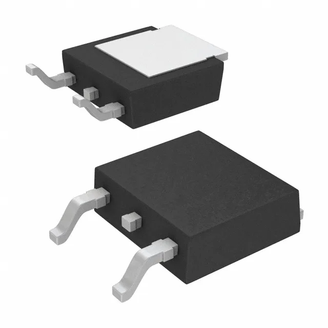
Package and thermal path — TO-252-3 (DPak)
Housed in a TO-252-3 (DPak) surface-mount package, supplier code PG-TO252-3-11. The tab is large enough to wick heat into the board, but the part's 175°C maximum junction temperature gives headroom for high ambient or constrained airflow. Rework is straightforward with hot air: the tab soaks heat evenly, and the three leads are clearly visible for alignment.
This exceeds the standard automotive Grade 1 range (-40°C to 150°C) on the high end, suiting it for under-hood electronics, engine bay modules, and industrial motor drives where the local ambient near the heatsink can push past 125°C. The 100 V drain-source rating provides margin for 48 V and 72 V nominal bus systems, including the transients on a 48 V automotive mild-hybrid rail or a 72 V industrial DC bus.
ROHS3 compliant.