The IPD50N06S214ATMA2: That figure is the hot ceiling at 25 °C junction — actual Rds(on) rises with temperature, so a 50 A design should budget roughly 1.5× the room-temperature Rds(on) at full load and 125 °C junction. The total gate charge of 52 nC at 10 V means a gate driver delivering 1 A peak can switch the FET in about 50 ns, which keeps crossover losses manageable at switching frequencies up to 100-200 kHz.
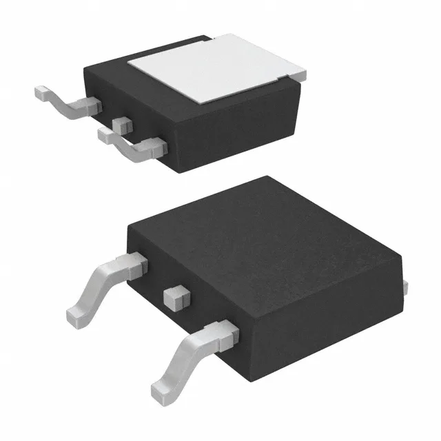
TO-252-3 DPak — footprint and thermal pad
The part comes in the standard TO-252-3 (DPak) surface-mount package, supplier device code PG-TO252-3-11. The exposed drain tab on the bottom needs a copper pad on the PCB — the datasheet's recommended footprint and thermal-via pattern are what keep the junction temperature below 175 °C at 50 A. The package accepts standard reflow profiles; MSL level should be confirmed on the reel label before the bake decision.