100 V, 27 A — the conduction-loss anchor
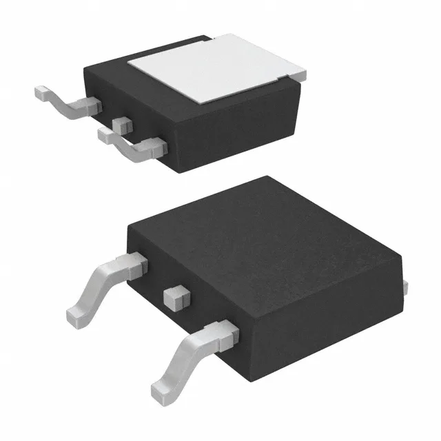
This is a 100 V class part, which gives roughly 50% headroom on a 48 V bus and comfortable margin on 24 V or 12 V rails where transients can spike to 60-80 V. The 27 A continuous rating assumes the TO-252-3 DPak package is soldered to adequate copper area on the PCB to pull heat from the exposed tab.
Gate charge and switching — 24 nC at 10 V
For a hard-switched converter at 200 kHz, the gate drive current needed is about 4.8 mA average — easily handled by a standard MOSFET driver.
Thermal reach: 175°C junction and 58 W dissipation
In a still-air environment with minimal copper, derate to 2-3 W continuous.
Supplied in a TO-252-3 (DPak) surface-mount package, supplier device package PG-TO252-3.
RoHS3 compliant, which covers the full ten restricted substance categories under EU directive 2015/863.