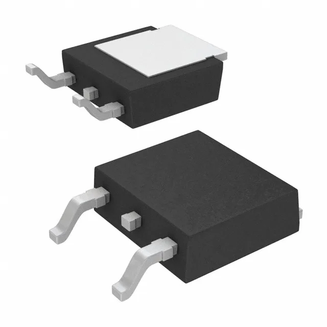
200 V, 34 A N-channel — the Rds(on) that sets the thermal budget
For a 48 V telecom brick or a 72 V battery-powered auxiliary converter, this Rds(on) class keeps the TO-252 package's 136 W power dissipation ceiling in play without pushing into the derating curve prematurely.
Gate charge and switching — 29 nC at 10 V
The input capacitance Ciss of 2350 pF at 100 V Vds gives a rough Miller plateau charge of about 10 nC, so the driver's peak current capability matters more for the turn-on/turn-off edges than the average current. Design the gate-drive loop with a 10 V rail and a low-inductance path to the TO-252 source tab.
175 °C junction — headroom for constrained airflow
For a power MOSFET in a TO-252 (DPak) surface-mount package, that 175 °C ceiling is the key derating parameter: at 100 °C ambient with minimal forced air, the allowable power dissipation drops from the 136 W Tc-rated maximum to roughly 60–70 W depending on the board copper area under the tab.
It is ROHS3 compliant. No official second-source or direct replacement is listed on the Infineon cross-reference, so dual-sourcing requires a parametric search for a 200 V, 34 A, 32 mOhm N-channel in a compatible DPak footprint.