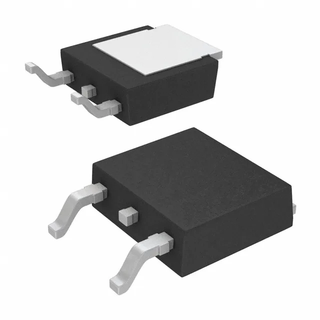
The 25 mOhm maximum on-resistance at a 10 V gate drive defines the conduction loss floor — at 35 A that is roughly 30 W dissipated in the die, which the TO-252 package must sink through the exposed drain tab to a copper plane.
Gate charge and switching — 31 nC at 10 V
Total gate charge is 31 nC at a 10 V gate drive. This is moderate for a 100 V / 35 A device — the driver sees about 3.1 mA per 100 kHz of switching frequency, which a standard totem-pole gate driver handles without a heatsink. The input capacitance of 2070 pF at 50 V drain-source sets the Miller plateau slope; expect a few hundred nanoseconds of switching time in a hard-switched buck or boost converter.
Package and footprint — PG-TO252-3
The PG-TO252-3 package (DPak, two leads plus tab) is a surface-mount medium-power outline.