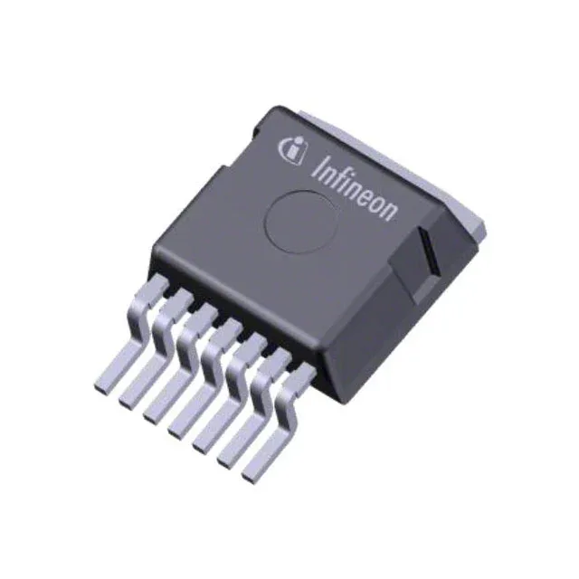
The IPBE65R099CFD7AATMA1: At 12.5 A drain current with 10 V on the gate, the maximum on-resistance is 99 mOhm. That is the number to plug into the conduction-loss calculation: I² × Rds(on) × duty cycle. The 127 W power dissipation rating at the case gives the absolute ceiling.
Gate charge and switching — 53 nC at 10 V
That sets the gate-driver power requirement: Qg × Vgs × fsw. The 2513 pF input capacitance at 400 V drain-source is the capacitive load the driver sees.
Package and mounting — PG-TO263-7
Surface-mount in a TO-263-7 D²Pak (PG-TO263-7-3-10). The large tab is the drain connection and the primary thermal path. Solder the tab to a copper plane on the PCB — the thermal resistance to the board depends on the pad size and via count. The 6-lead plus tab footprint is standard for this class; verify the land pattern against the supplier package drawing before the PCB layout is frozen.
The 150°C TJ max is the hard limit for thermal shutdown in the design.