The 39 nC total gate charge at 10 V is the figure that determines the gate-driver current needed for a target switching frequency. A 39 nC gate charge switched at 100 kHz draws 3.9 mA average from the driver, well within the capability of most half-bridge gate-drive ICs. The input capacitance of 710 pF at 100 V Vds helps estimate the driver's peak current requirement during the Miller plateau.
Package and thermal — the D²Pak footprint
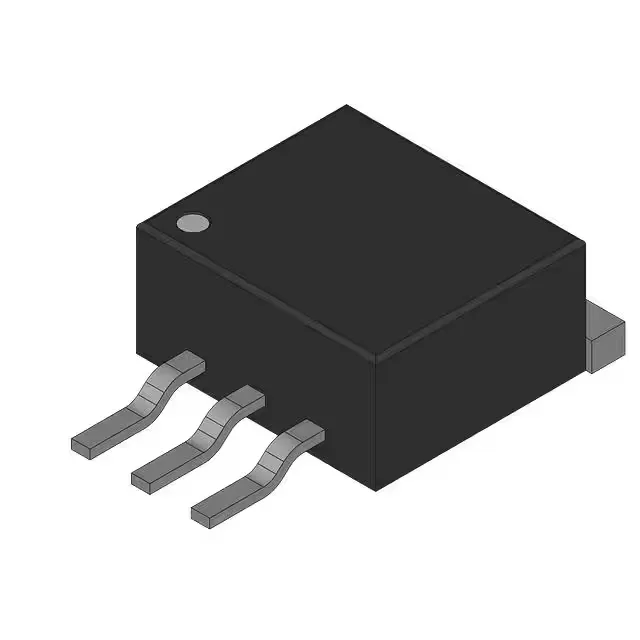
The IPB65R380C6 is supplied in the TO-263-3 (D²Pak) surface-mount package, supplier device code PG-TO263-3-2. The exposed metal tab on the bottom is the drain connection and the primary thermal path — the PCB copper area under the tab sets the junction-to-ambient thermal resistance. The 83 W maximum power dissipation at case temperature assumes a good thermal connection to a heatsink or large copper pour. The gate-source voltage rating is ±20 V absolute maximum, so a 10 V gate drive is within the safe operating area with margin for ringing.
ROHS3 compliant. No official successor or replacement has been issued, which is consistent with an active part that remains in the portfolio.