Rds(on) at junction temperature — the real conduction loss number
The IPB180N04S4H0ATMA1 lists a maximum Rds(on) of 1.1 mOhm at 100 A with 10 V gate drive, but that figure is specified at 25 °C junction. At a 125 °C junction temperature — typical in a high-current motor drive or synchronous rectifier — the on-resistance roughly doubles. The buyer should budget for an effective 2.2 mOhm or more at operating temperature and size the PCB copper area accordingly.
Gate charge — what it costs to switch 180 A
Total gate charge is 225 nC at 10 V.
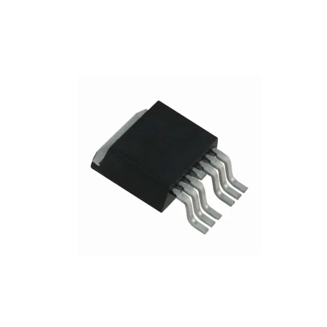
The PG-TO263-7-3 package (D²Pak with 6 leads plus tab) is a surface-mount power package.
It is ROHS3 compliant.