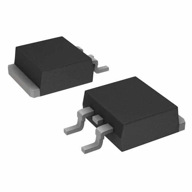
Conduction loss and gate drive budget
The 87 nC total gate charge at 10 V means a 100 kHz switching frequency draws about 8.7 mA average from the gate driver; a 1 A driver handles it easily, but the gate-drive loop inductance and resistance matter for clean turn-on. Input capacitance Ciss is 7100 pF at 100 V drain — this sets the switching energy per cycle and the driver's peak current requirement.
For 88 A continuous, a multi-layer board with thermal vias and a heatsink on the bottom side is expected; the 300 W maximum dissipation at case temperature is a die limit, not a free-air number.
ROHS3 compliant.