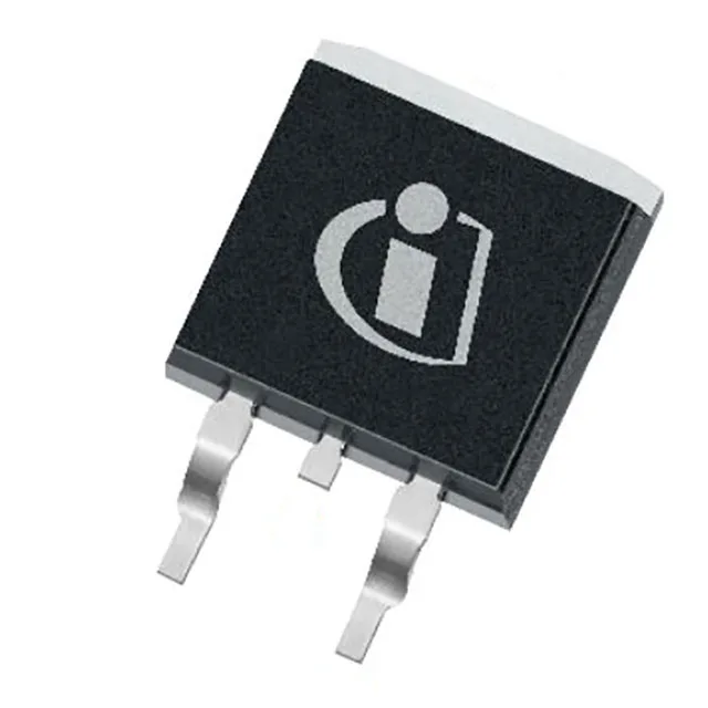
100V N-channel with 4.35 mOhm Rds(on) — the conduction loss floor
The IPB043N10NF2SATMA1: This is the part's defining parametric — the Rds(on) at the operating point sets the conduction loss for the power path. The 135 A continuous drain current at the case temperature (Tc) tells you the package and die can handle high steady-state current, but the junction-to-case thermal path in the PG-TO263-3 package is what makes that rating real: the 167 W power dissipation at Tc is the thermal budget ceiling for the heatsink design.
Gate charge and switching drive budget
Total gate charge is 85 nC at 10 V. The input capacitance is 4000 pF at 50 V Vds.
Automotive-grade temperature envelope
The 175 °C TJ max is the ceiling for the die attach and mold compound; the 3.8 W at ambient (Ta) power dissipation is the free-air limit with no heatsink — useful for low-duty-cycle or fault-condition checks. The threshold voltage of 3.8 V maximum at 93 µA drain current gives the turn-on margin for a 10 V gate drive, but at 6 V drive the Rds(on) is higher per the drive voltage spec.