Active production — stable BOM line item
The IPA086N10N3GXKSA1: BOM planners can treat this as a design-in stable line item for new builds and sustaining production alike.
100 V, 45 A, 8.6 mOhm — switching and conduction loss profile
These numbers drive the gate driver's peak current and switching loss budget: a 100 kHz hard-switched application drawing 55 nC per cycle needs an average gate drive current of 5.5 mA plus the crossover loss from the Miller plateau.
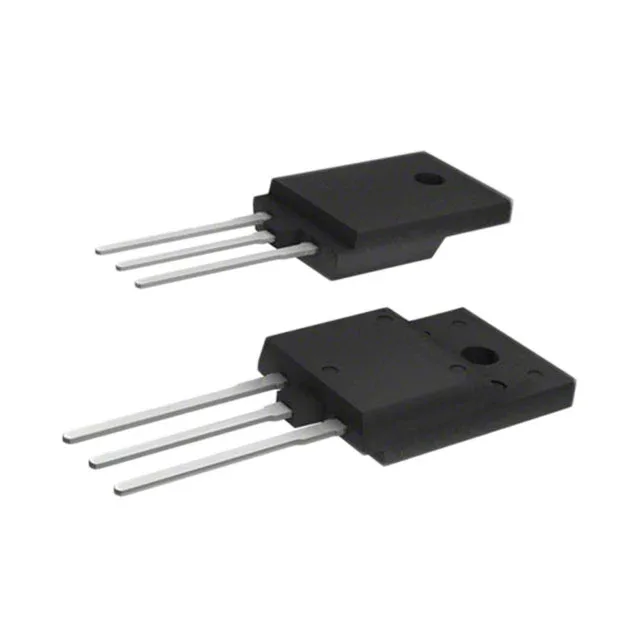
TO-220 Full Pack — isolated mounting, no insulating washer
The PG-TO220-FP (Full Pack) package encapsulates the backside tab in moulding compound, so the heatsink interface is electrically isolated. No insulating pad or shoulder washer is needed — the device mounts directly to a grounded chassis or heatsink, saving assembly time and thermal interface material cost. The through-hole leads suit wave-solder or hand-solder assembly.
The junction temperature range spans -55°C to 175°C, which covers MIL-STD-883 Class B and most avionics, downhole, and engine-bay profiles. The 175°C absolute maximum junction temperature is the hard ceiling for thermal runaway protection — the 37.5 W dissipation limit at case temperature must be derated above 25°C per the datasheet's thermal impedance curve.
Gate drive: 6 V minimum for rated Rds(on)
The drive voltage range is 6 V to 10 V for the rated on-resistance. Designs using a 5 V gate rail should budget for increased conduction loss or step up to 10 V via a gate driver with bootstrap or charge-pump output.